Exercise 1: Define Elements, Real Constants, Materials, Properties, and Components
In this exercise you will learn about the ANSYS FE input reader, template, macro menu, and user profile which set the foundation for using ANSYS with HyperMesh.
Load the ANSYS User Profile
In this step, you will load the ANSYS user profile in HyperMesh.
- Start HyperWorks.
- From the menu bar, click .
Retrieve the Model File
In this step, you will retrieve and open the model file in HyperMesh.
- Optional:
If your model's elements and mesh lines are not shaded, click
 on the View Controls toolbar then select
  .
.
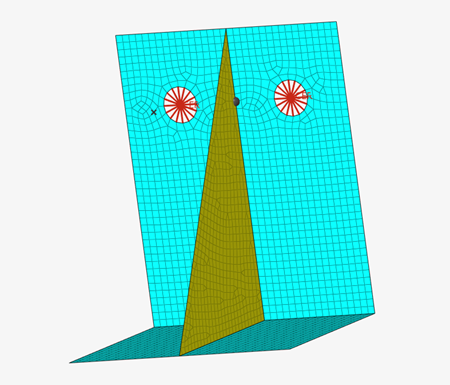
Figure 1.
Add an Element Type
In this step, you will add an element type in HyperMesh.
-
In the Model Browser, right-click and select from the context menu.
HyperMesh creates and opens a sensor (Et Type) in the Entity Editor.
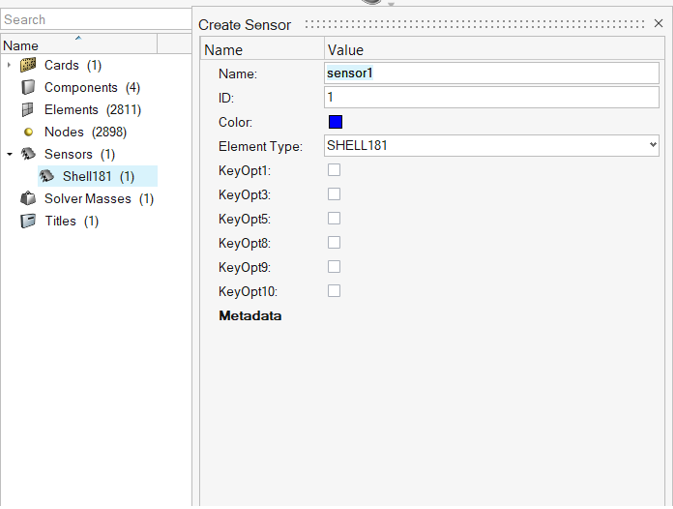
Figure 2. -
For Element Type, keep SHELL181.
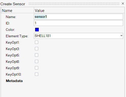
Figure 3.- SHELL181
- Suitable for analyzing thin to moderately-thick shell structures. It is a 4-node element with six degrees of freedom at each node: translations in the x, y, and z direction; rotations about the x, y, and z axes (if the membrane option is used, the element has translational degrees of freedom only). The degenerate triangular option should only be used as filler elements in mesh generation.
Note: By default, HyperMesh set the Element Type to SHELL181. The elements in this model are of type SHELL181, therefore you do not need to change the element type for this tutorial. -
Set the element stiffness (KeyOpt1), integration (KeyOpt3), layer data storage
(KeyOpt8), thickness (KeyOpt9), and/or initial stress (KeyOpt10) options by
selecting their corresponding checkboxes in the Value column as indicated in
Figure 4.
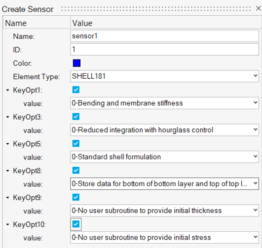
Figure 4.A value appears below each KeyOpt you selected. -
In the Solver Browser, review the ET Type you
created.
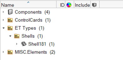
Figure 5.
Define Material Properties
In this step, you will define the properties of a material.
-
In the Model Browser, right-click and select from the context menu.
HyperMesh creates and opens a material in the Entity Editor.
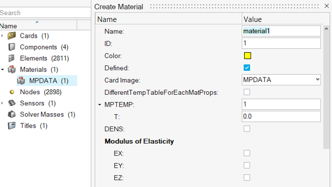
Figure 6. -
Set card image to
MATERIAL.
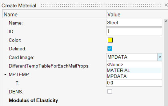
Figure 7. -
For MP_EX_LEN (Number of Elastic moduli to input), enter
1.
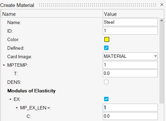
Figure 8. -
For C, enter 2.1e5.
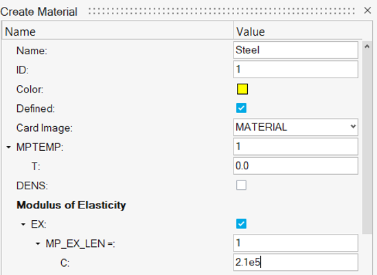
Figure 9.
Create the Section Card for the Shell Elements in the Model
In this step, you will create a section card for the model shell elements.
-
In the Model Browser, right-click and select from the context menu.
HyperMesh creates and opens a property in the Entity Editor.
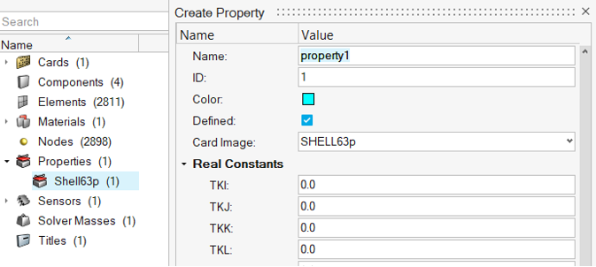
Figure 10. -
For MAT, click .
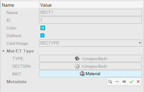
Figure 11. -
In the new Entity Editor, change the config to
Shell, set the Tk value to
0.5, then click Previous.
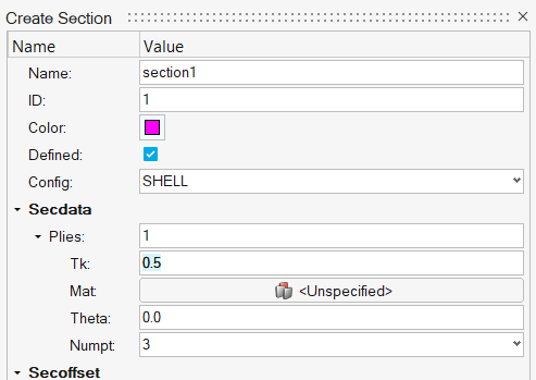
Figure 12. -
Click the search icon then assign sensor1.
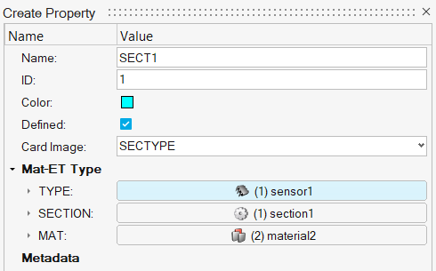
Figure 13. -
Go to the Solver Browser and review the two sections you
created.
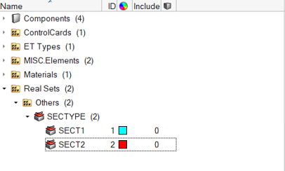
Figure 14.
Update Each Component
In this step, you will update each component with the respective element type, property, material, and section information.
-
In the Component folder of the Model Browser, click
Base.
The Entity Editor opens and displays the component's corresponding data.
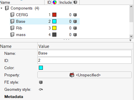
Figure 15. -
In the Select Property dialog, select
SECT1.
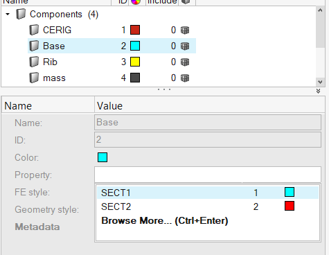
Figure 16. -
Create a property card that associates a small mass to the mass elements.
-
Right-click on Property and select
Create/Edit from the context menu.
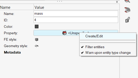
Figure 17. -
Under Real Constants, enter 0.001 for
MASS.
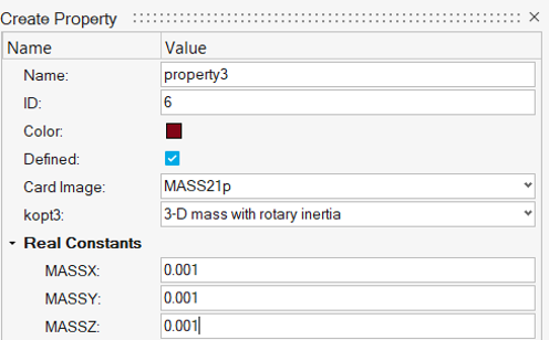
Figure 18.
-
Right-click on Property and select
Create/Edit from the context menu.
Save Your Model
In this step, you will save the model to your working directory.
- From the menu bar, click .
- In the Save Model As dialog, navigate to your working directory and save the file.