HS-1650: Beam Cross-Section Study with Inspire Studio
In this tutorial, you will perform geometric changes in Inspire Studio via HyperStudy and study the effect of each dimension on responses.
- Use Inspire Studio to change dimensions of an I-beam cross-section and generate a new CAD file.
- Read the CAD file into HyperMesh and prepare a finite element model via automation script.
- Run the finite element model in OptiStruct and extract displacement results.
- Width
- Height
- Web Thickness
- Flange Thickness
- Hexahedral Mesh
- Fixed in all directions at one end
- Bending load applied in positive Y direction at the other end

Figure 1.

Figure 2.
Specify Design Variables in Inspire Studio
Setup Inspire Studio Model
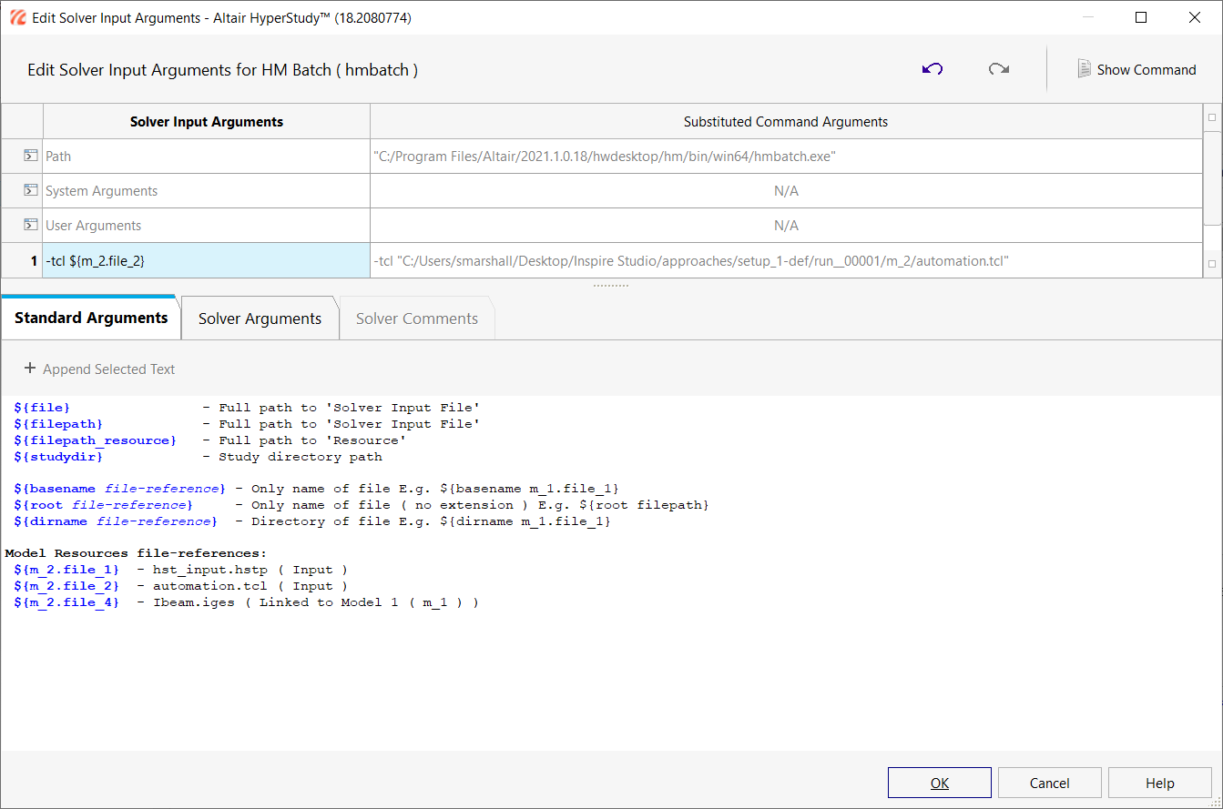
Setup HyperMesh Batch Operator Model
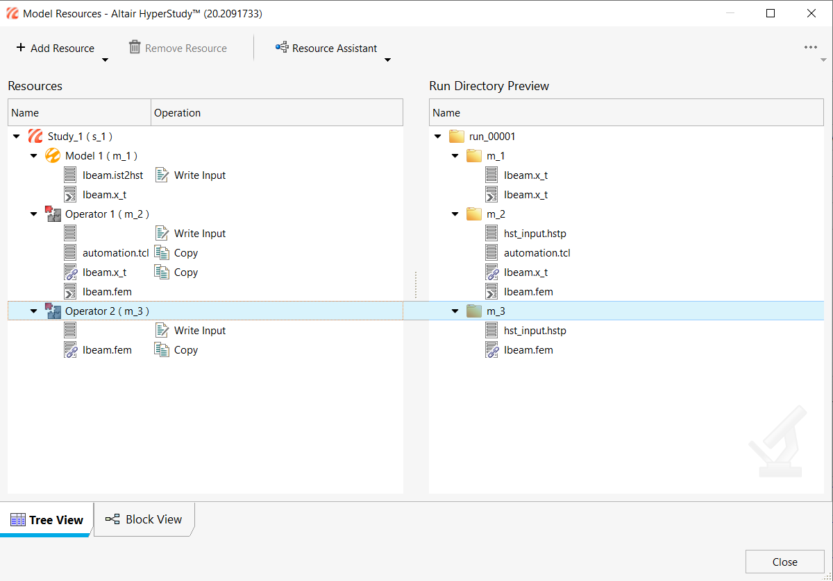
After the Inspire Studio Model run is complete, a geometry file, Ibeam.iges, is output. This file is read by HyperMesh and a finite element model (Ibeam.fem) is prepared via the automation.tcl script in the working directory.
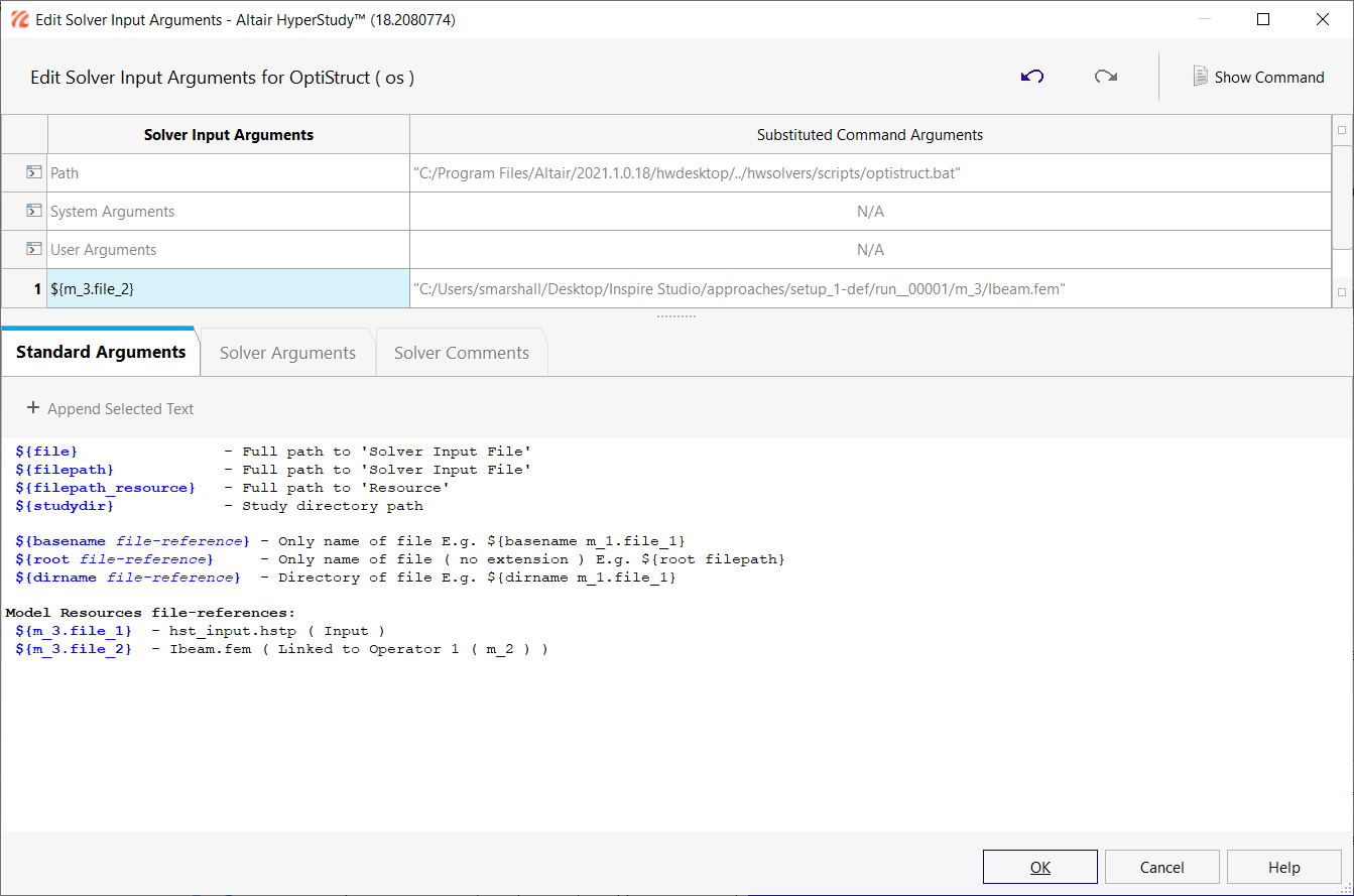
Setup OptiStruct Operator Model
After the HyperMesh Operator Model run is complete, an input file (Ibeam.fem) is created to be used for finite element analysis in OptiStruct.
Create Output Response
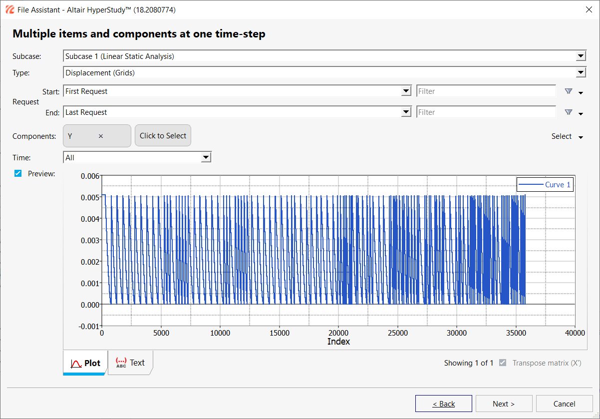
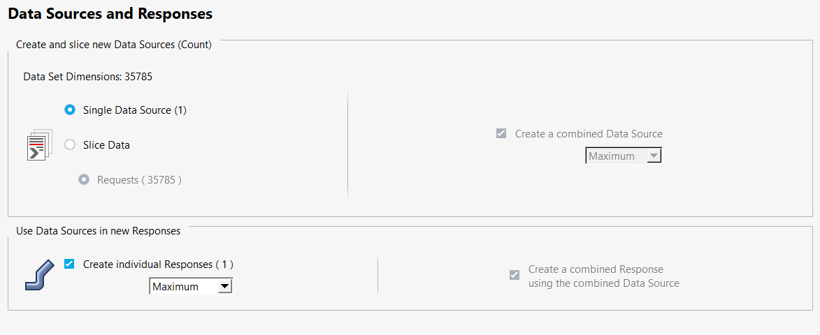
In this step, you will create a single output response: Maximum Displacement of all nodes in Y direction.
- Go to the Define Output Responses step.
-
Create the Maximum Displacement output response.
- Click Evaluate.

 .
.


