Tagpoint Mapping Tool
Allows automated mapping/creation of tagpoints and connections between data from different sources.
- Metadata-FE
- FE-FE
- CSV-FE
- Tagpoint template CSV

Figure 1.
Metadata-FE
- Scan from 10th field grids
- 10th field entry in the GRID point definition of FE data is used for scanning.
- Scan from HM Tags
- This option is used in Prepare Module to scan HM tags in FE data.
- Scan from metadata node Ids
- Matching nodes ID's in FE data and metadata are used for scanning.
- Scan from FE node locations
- User specified tolerance is used for scanning the node information between FE and metadata.

Figure 2.
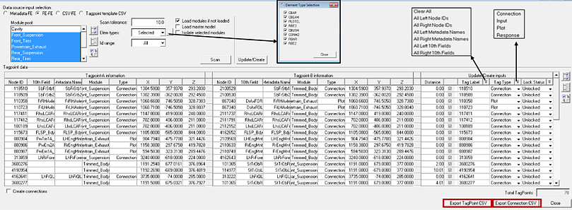
The information related to Node IDs, Coordinates and the Tab label can be updated from metadata to FE, and vice versa. The arrow mark directions controls the database to be updated. The nodes to be updated are selected using the checkbox option. There is an option to select the tag type. The database is updated using the Update/Create button. Updated information is highlighted using color coding. The light green color indicates a database update from FE to metadata and the dark green color indicates a database update from metadata to FE.
The Export Tagpoint CSV option is used to export the mapped tagpoints to an external .csv file.
Fe-Fe
This option is used to map/create the tagpoints between different modules based on the scanned nodes within user specified tolerance ranges. This is very useful in the identification of potential connection points across modules when you are building a fresh assembly with modules without any tagpoints. Tagpoints can be created automatically at identified connections points. There is also an option to create connections between the created tagpoints. Tagpoints are mapped for the selected modules from Module pool at nodes which are scanned and identified within the specified tolerance. There is also an option to limit the scan to nodes referenced by specific element types. Node pairs between different modules within the scanned tolerance are populated in the table with associated information like node ID, 10th Field information, metadata name, owning module and coordinates.
Select the node pairs with the checkbox option. Expand the Tag Label to select the options to be used as tag labels for the created tagpoints. You can also type in the tag label. The Update/Create button creates the tagpoints. Tag label and all the relevant information for tagpoints is updated. Activate the Create connections checkbox to create connections between created tagpoints.

Figure 3.
CSV-FE
This option is used to map/create tagpoints based on information from a tagpoint CSV or a connection .csv file. This allows you to effectively use information from the previous session saved in a tagpoint/connection .csv file for new assembly building. The information in the .csv file, tagpoints or connections, is loaded on the left side of the separator, depending on the .csv file that is loaded.

Figure 4.
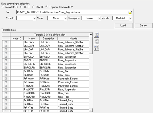
Tagpoint Template CSV

Figure 5.

Figure 6.