OS-E: 3040 Forge a Design Reference Out of a Solid Block
Pattern grouping lends itself very well to applications where manufacturing conditions must be met. In this example, topography optimization is used to form a design concept out of a solid block. Manufacturing the design concept using a casting method is preferable.
Model Files
Refer to Access the Model Files to download the required model file(s).
- block.fem
- blocklong.fem
Model Description
All optimization set up is done using the Optimization panel and its subpanels in HyperMesh.
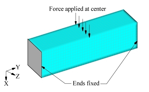
Figure 1. Loads and Constraints for the Solid Block Model
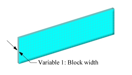
Figure 2. User-Defined Variable #1
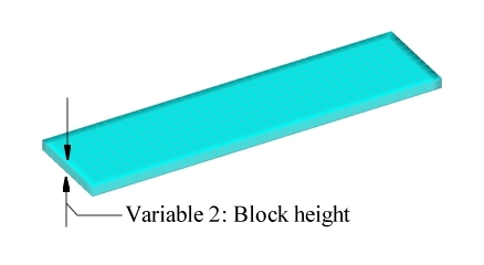
Figure 3. User-Defined Variable #2
It is preferable to manufacture the resulting part using a casting process. This can be accomplished by using a linear pattern grouping in the casting draw direction and a planar pattern grouping perpendicular to the draw. This will ensure that there are no cavities that would create a die lock situation.
| (1) | (2) | (3) | (4) | (5) | (6) | (7) | (8) | (9) | (10) |
|---|---|---|---|---|---|---|---|---|---|
| DTPG | 3 | DVGRID | 1 | ||||||
| + | 2.0 | 60.0 | NO | ||||||
| + | PATRN | 21 | 50.0 | 250.0 | 50.0 | 0.0 | 0.0 | 1.0 | |
| + | PATRN2 | 0.0 | 1.0 | 0.0 |
| (1) | (2) | (3) | (4) | (5) | (6) | (7) | (8) | (9) | (10) |
|---|---|---|---|---|---|---|---|---|---|
| DESVAR | 1 | DV001 | 0.0 | 0.0 | 1.0 |
| (1) | (2) | (3) | (4) | (5) | (6) | (7) | (8) | (9) | (10) |
|---|---|---|---|---|---|---|---|---|---|
| DTPG | 4 | DVGRID | 2 | ||||||
| + | 20.0 | 60.0 | NO | ||||||
| + | PATRN | 13 | 50.0 | 250.0 | 50.0 | 0.0 | 1.0 | 0.0 |
| (1) | (2) | (3) | (4) | (5) | (6) | (7) | (8) | (9) | (10) |
|---|---|---|---|---|---|---|---|---|---|
| DESVAR | 2 | DV002 | 0.0 | 0.0 | 1.0 |
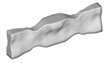
Figure 4. OptiStruct Solution for the Solid Block
Results
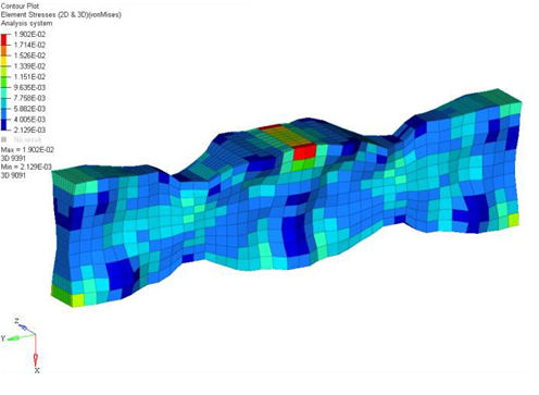
Figure 5. Stress Contours for the OptiStruct Solution
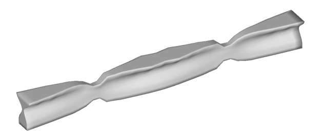
Figure 6. OptiStruct Solution for Solid Block with 2.5 Times Smaller Cross-Section
The basic shape of the block is the same in the reduced dimension model, but has more pronounced features. The I shaped cross-sections in the center and at the ends have wider flanges, and the shear carrying areas in between are thinner. This makes sense considering the smaller dimensions increase the need for bending stiffness more than the need for shear stiffness.