RD-E: 2603 Forming
Failure criteria defined with failure model /FAIL/FLD.
In Radioss it is possible to simulate failure with a failure model. FLD failure models are most commonly used for forming, which describe material failure in strain space. Here, one shell element and circular plate model are used to demonstrate the failure behavior with FLD failure model.
Options and Keywords Used
- Johnson-Cook failure model (/FAIL/JOHNSON)
- Forming Limit Diagram failure model (/FAIL/FLD)
- Imposed velocities (/IMPVEL)
- Material LAW2 (/MAT/LAW2 (PLAS_JOHNS))
- Rigid sphere (/RWALL)
Input Files
Refer to Access the Model Files to download the required model file(s).
The model files used in this example are available in:
/radioss/example/26_Ruptured_plate
Model Description
FLD Failure Model (Forming Limit Diagram)
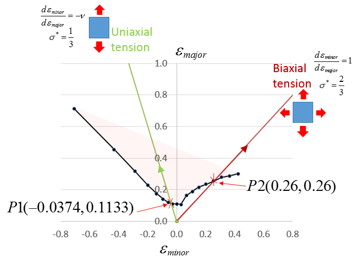
Figure 1.
- In uniaxial test (by ) once point P1 (-0.0374,0.1133) is reached, the element fails
- In eqibiaxial test (by ) once point P2(0.26,0.26) is reached, the element fails
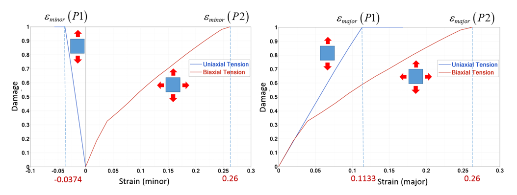
Figure 2.

Figure 3.
Only with /ANIM/SHELL/FLDF and Ifail_sh=4 is it possible to compute just the damage and not delete the element. It used to have a better vision of dangerous zones.
Results
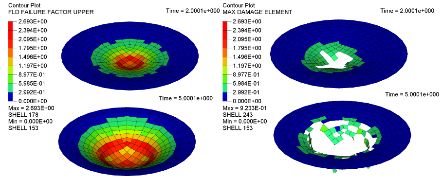
Figure 4.
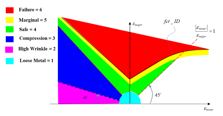
Figure 5. Failure zone
- FLDZ=6
- Failure
- FLDZ=5
- Marginal
- FLDZ=4
- Safe
- FLDZ=3
- Compression
- FLDZ=2
- High wrinkle
- FLDZ=1
- Loose metal
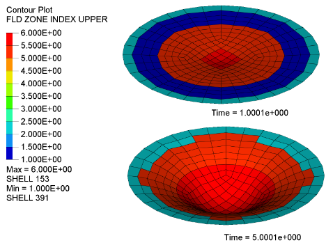
Figure 6. Failure zone in plate test
Conclusion
Failure model /FAIL/FLD used principal strain ratio to describe the material failure behavior which is suitable to describe material failure in forming.