Tutorial: Introduction to Modeling with Arduino Boards
Learn how to create a model and generate code that controls an LED light on an Arduino Uno board.
Files for This Tutorial
button_led_2sec.scm
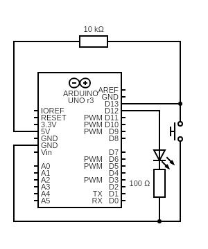
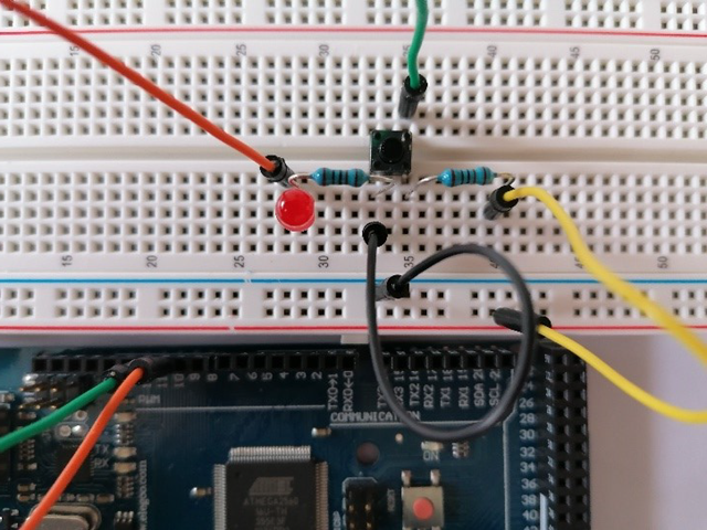
Overview of the Hardware and Circuit
These components are required to complete the tutorial:
Hardware
- Arduino Uno board
- Breadboard + wiring for connecting components
- LED light
- 10K-ohm resistor
- 100-ohm resistor
Circuit
Create the Activate Model
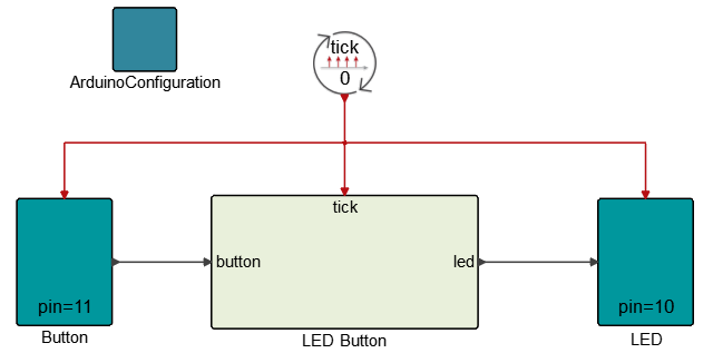
- Arduino Configuration block: This block is set in simulation mode to open the serial communication port with the Arduino board.
- Button block: This block represents the hardware button connected to pin 11 on the Arduino board.
- LED block: This block represents the hardware to which the LED light is connected to pin 10 of the Arduino board.
- LED Button super block: This block contains the dynamics of the system, including the super blocks led off and led on. When the button is pressed, the LED light switches on for two seconds, then switches off automatically.
The model uses a state machine construction method in Activate, which enables the model to include two different states: one where the light is on (defined by the super block led on) and another where the light is off (defined by the super block led off). The led on and led off super blocks are located inside of the LED Button super block.
See the Activate Extended Definitions for more information on the state machine construction method.
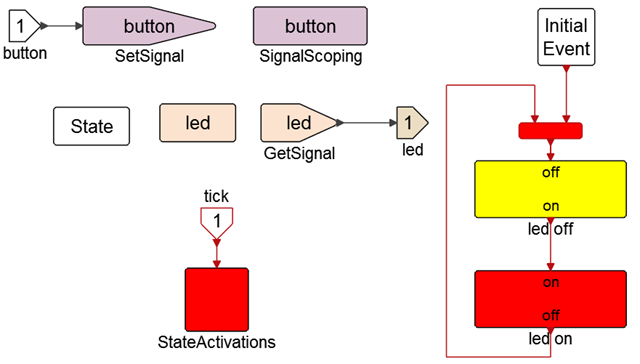
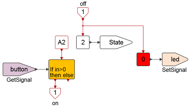
Initially the led off super block is activated through its activation input port. This process changes the state number to 2 and sets the led signal to zero. Subsequent activations come through the activation signal A2. No output activation is generated until the button signal becomes positive. Once the output activation is signaled on, it enters the led on super block.
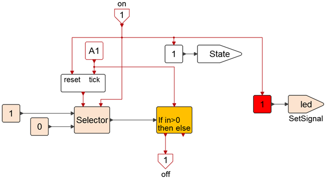
The on signal changes the value of the state to 1, and thus deactivates the state represented by the led off super block and activates the led on super block state. It also sets the signal led to 1, which turns on the LED light and resets the counter.
The subsequent and successive activation of A1 signals then increments, through tick input, the counter until the desired value is reached, which in this case is 2 seconds.
Steps for Simulation
Steps for Code Generation
-
Create a super block to contain the top level diagram.
- Select all blocks that are at the top level of the diagram.
-
Click the Super Block tool
 and create a super block with the selected
blocks.
and create a super block with the selected
blocks.