Tutorial: Designing a Circuit with Spice Components
Learn how to design a circuit with a Band Pass Filter using Spice components.
Files for This Tutorial
aop.lib; BandPassFilter.scm, filter.scm; OP_NON.cir*
* The file OP_NON.cir is a non-inverting amplifier model
provided for you with permission from the eCircuit Center http://www.ecircuitcenter.com/Circuits/opmodel1/opmodel2.htm. In lieu of downloading the file, you can copy the following
code as required in the steps of the
tutorial.
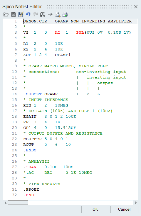
OPNON.CIR - OPAMP NON-INVERTING AMPLIFIER
*
VS      1       0      AC      1      PWL(0US 0V  0.1US 1V)
*
R1      2       0      10K
R2      2       4      10K
XOP     1 2     4      OPAMP1
*
* OPAMP MACRO MODEL, SINGLE-POLE
* connections:      non-inverting input
*                   |   inverting input
*                   |   |   output
*                   |   |   |
.SUBCKT OPAMP1      1   2   6
* INPUT IMPEDANCE
RIN      1      2      10MEG
* DC GAIN (100K) AND POLE 1 (10HZ)
EGAIN    3 0    1 2    100K
RP1      3      4      1K
CP1      4      0      15.915UF
* OUTPUT BUFFER AND RESISTANCE
EBUFFER  5 0    4 0    1
ROUT     5      6      10
.ENDS
*
* ANALYSIS
.TRAN    0.1US  10US
*.AC     DEC     5 1K 10MEG
*
* VIEW RESULTS
.PROBE
.END
Overview of the Spice Circuit Model
In this tutorial, you will construct a circuit out of blocks from the HyperSpice palette.
Create a Model with a Spice Custom Block
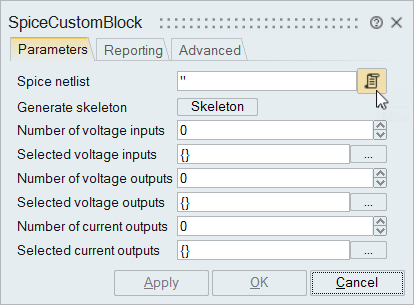
Add a SpiceCustomblock and Scope block to you model.
-
From the Parameters tab, select the SPICE Netlist button.
The Spice Netlist Editor appears. -
Copy the code from the OP_NON.cir file and paste it into
the Spice Netlist Editor.
-
From the Parameters tab, select the button to define the Selected
voltage outputs.
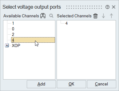
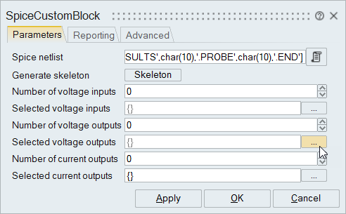 The Select voltage output ports dialog appears.
 -
From the list of Available Channels, double-click
4.
-
Drag one Scope block into your diagram and connect it to
the output of the SpiceCustomBlock.
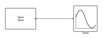
This portion of the model is ready to run and test. -
From the Run
 tool, select Setup
  .
.
-
Click Run
 .
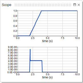
Double-click the Scope block in the model. The plot should look something like this:
.
Double-click the Scope block in the model. The plot should look something like this: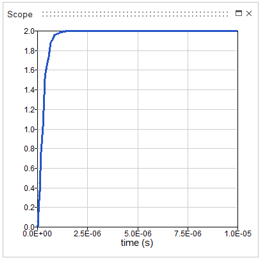
Create a Spice Model from a Modelica Model
Create a circuit with components from the HyperSpice palette. Base your model on the Modelica example that is provided.
-
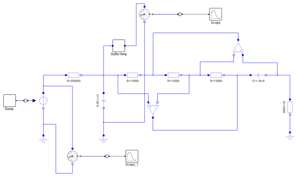
From the Demo Browser, select BandPassFilter.scm
The BPF model constructed from Modelica blocks appears.
-
Beginning with the Filter.scm model you started, construct
a Spice version of the circuit model using the blocks from the HyperSpice
palette.
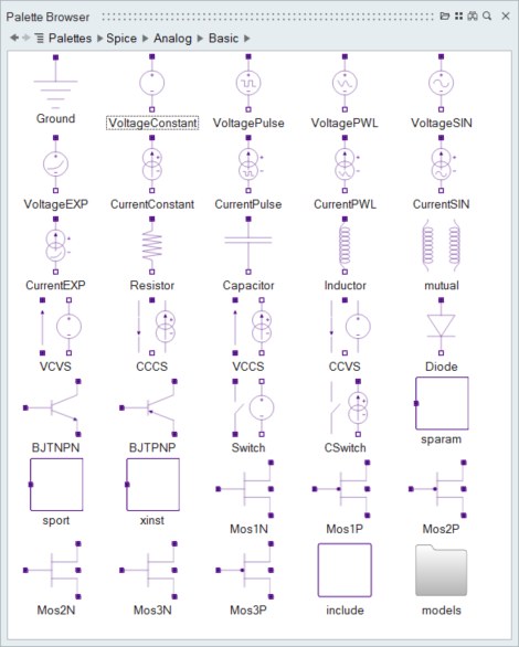
To create these components in your model Include these blocks from the HyperSpice palette Voltage and current stimulus Voltage Constant; Voltage Pulse; Voltage SIN Linear components Resistor; Capacitor; Inductor Voltage and current constant sources Include blocks as required for your model. Semiconductor components Diode; BJTNPN; BJTPNP; Mos1N; Mos1P; Mos2P; Mos2N; Mos3N; Mos3P Sub circuits Include blocks as required for your model. Cable or S-parameter functions Include blocks as required for your model. Refer to the Extended Definitions to define the blocks.
Complete the Spice Model
Add an xinst block to your model and reference the block through a Spice.lib file.
-
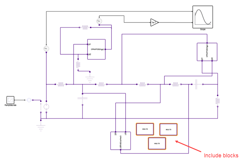
Because three operational amplifiers are required for your model, three include
blocks are also required. To duplicate the current include block, select it and
press Ctrl+D two times.
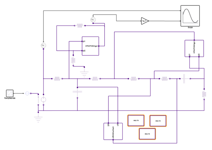
Your final model should look something like this:
Simulating the Diagram
-
From the Run tool, select Setup .
-
Click Run
.
To view the transient results, double-click the Scope block in the model. The plot should look something like this: