In a belt-pulley system, a long flexible belt is used to transmit mechanical power by
wrapping the belt around rotating pulleys. The power is transmitted due to friction between
the belt and pulley surface. The belt-pulley subsystem in MotionView helps assemble such a system very quickly with a minimal
inputs such as pulley center position, radius, and belt properties.
A belt-pulley needs the following entities to be present in
the model.
- A reference marker, such as that the XZ plane of the marker coincides with the
plane formed by the pulley, centers when the belt-pulley system lies in a plane
other than the global XZ. In the case of an NLFE belt formulation, the XZ plane
has to be parallel to the global XZ plane.
MotionView offers two types of belt-pulley systems:
In both cases, the system is modeled in such a way that the pulley centers lie in the
XZ plane of the reference marker used to model the system.
Note: An NLFE belt currently can only be modeled such that the Y-axis of belt-pulley
system marker reference is parallel to the global Y. This limitation will be removed
in a later release.
-
From the Subsystems toolbar, click the Belt Pulley
Subsystem toolbar icon
 .
.
The Add a Belt-Pulley Subsystem dialog is
displayed.
-
Click the System collector and decide which system the
belt/pulley needs to be created in.
-
Specify a variable name and label for the belt/pulley.
By default, variable names of entities in MotionView follow a certain convention. For example, all belt/pulley entities have a
variable name starting with bp_. This is the recommended
convention to follow when building models in MotionView since it has many advantages in model editing
and model manipulation.
-
Select the type of belt formulation to represent the belt using the drop-down
menu.
-
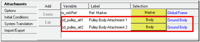
If a reference frame other than global frame is to be used, select the
reference marker for pulley coordinates by double-clicking on the
Marker collector (located in the lower, left of the
dialog).
The belt-pulley system will be created such that the assembly lies within the
XZ plane of the reference frame.
-
By default, two pulleys are available. To add or delete a pulley, use the
right-click option on a row item indicating the pulley number.
-
Enter values for the X and Z coordinates of the pulley center in the reference
marker coordinate frame.
-
Enter a value for the radius of the belt and specify which side (inner or
outer) of the belt loop the pulley is positioned from the drop-down menu.
-
Specify the total number of pulleys to create.
As the pulley is added/deleted, this field will be automatically updated.
-
Enter values for the belt width and belt thickness in the text boxes on the
right side of the dialog.
-
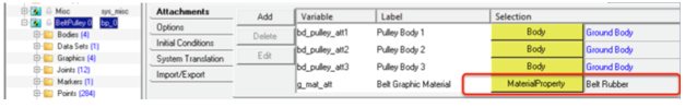
A linear elastic Belt Rubber material is available in
MotionView and is selected by default. To use a
different material, double click on the MaterialProperty
collector and select a different material from the list.
-
To create an NLFE belt formulation, complete the steps below:
-
In the NLFE Belt Component area, the minimum number of NLFE beam
elements required to accurately represent the belt based on the
calculated belt profile is displayed in blue. By default, the minimum
number of required elements is used. To use more elements, deactivate
the Use minimum required option and specify the
number of NLFE beam elements to be created.
-
The effective diameter based on the calculated profile length of the
belt in the installed position is also displayed in blue. By default,
the dialog sets a value for the free diameter by a known amount of
offset from the installed free diameter. Deactivate the Use
calculated value option to provide a different value for
the belt free diameter.
Note: This number should be smaller than the installed belt diameter, so
that the belt is sufficiently pre-tensioned. The greater the
difference between the free diameter and the Installed diameter, the
more pretension is induced.
-
To create a Discretized rigid bodies belt formulation, complete these
steps:
-
In the Belt Stiffness Properties section of the dialog, enter tensile
stiffness and tensile damping values along the longitudinal direction of
the belt.
-
Enter bending stiffness and bending damping values along the bending
direction of the belt.
-
Enter a value for the pre-tension of the belt.
-
For the Belt Contact Properties (Impact) section, the parameters are
the same as that found in the Contact panel with Impact method. Refer to
the Contacts tool topic to learn more about each of the
parameters.
-
Once all the above information is entered, click OK to
create the belt-pulley system and exit the dialog.
The NLFE belt-pulley system that is created has the following
architecture:
| Entity |
Description |
| Bodies |
Rigid pulley bodies and an NLFE belt body consisting of a
series of nonlinear beam finite elements are
created. |
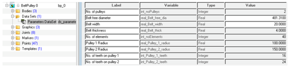
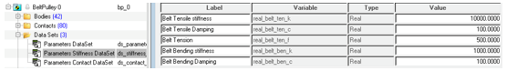
| DataSet |
A dataset where all editable values are stored. After the
creation of the belt-pulley system, you can change the free
diameter and width of the belt through this dataset. |
| Points |
The points that define the uninstalled belt profile and
the pulley centers. These are hidden by default. |
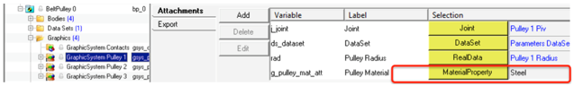
| Graphics |
The graphics for the pulleys. |
| Joints |
Revolute joints between the pulley and attaching body. In
addition, there are joints that connect the pulley and belt
body that help in transmitting motion. |
| Markers |
A reference marker to define the uninstalled
configuration of the belt (hidden by default). |
| Template |
Includes NLFE statements that are currently not supported
by MotionView. These include
GRIDS at the periphery of the pulley, LINE2 elements that
model contact between belt GRID and pulley GRID, and CONN1
elements that restrain the belt with the pulley along normal
of the belt-pulley plane. |
The discretized rigid bodies belt-pulley has the following architecture:
| Entity |
Description |
| Bodies |
Rigid pulley bodies and a belt body consisting of a
series of connected rigid bodies is created. |
| DataSet |
A dataset where all editable values are stored. After the
creation of the belt-pulley system, you can change the free
diameter and width of the belt through this dataset. |
| Points |
The points that define the uninstalled belt profile and
the pulley centers. These are hidden by default. |
| Graphics |
The graphics for the pulleys and belt. |
| Joints |
Revolute joints between pulley and attaching body. In
addition there are joints that connect the pulley and belt
that hold the belt in the system plane. |
| Markers |
A reference marker to define the uninstalled
configuration of the belt (hidden by default). |
| Template |
Includes MotionSolve command
statements to hide the graphics used in contact. |
Tip:
- Activate Show additional parameters to specify
variable names and labels for the points that are to be created.
- As the pulley X, Z, radii, and the belt side parameters are set, the preview
image shows the belt-pulley system configuration. The line joining the
pulleys tangentially represents the belt. For any incompatible information
(for example, overlapping locations of the pulleys, distance between two
pulley centers smaller than the summation of their radii) the belt line will
not be visible. Cross belt and out of plane pulley configurations are not
supported.
- To return to default settings, click Reset to
Defaults.