MV-1010: 3D Mesh-to-Mesh Contact Simulation
In this tutorial, you will learn about 3D rigid body contact capabilities in MotionSolve and use the mesh-to-mesh contact approach, which uses surface meshes for the bodies in contact during the simulation.
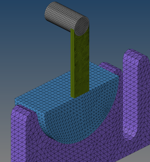
A surface mesh is an interconnected set of triangles that accurately represent the surface of a 3D rigid body. MotionSolve prescribes certain conditions for such a surface mesh.
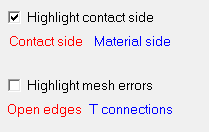
- Each component mesh should form a closed volume. This means that the given mesh should not contain any open edges (edge which is part of only one element) or T- connections (2 elements joined at the common edge in the form of a T).
- Mesh should be of uniform size.
- Element surface normal should point in the direction of expected contact.
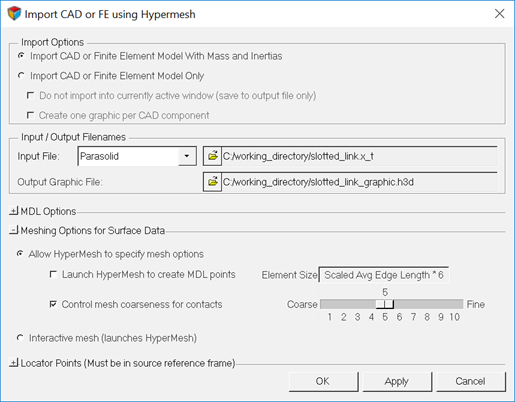
- Import CAD geometry with graphic settings suitable for contact simulation.
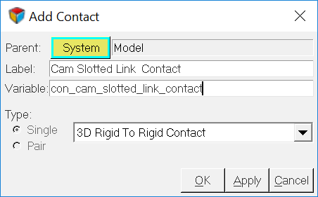
- Setup 3D rigid body contact between meshed geometries in the multibody model.
- Perform a transient analysis to calculate the contact forces between these geometries.
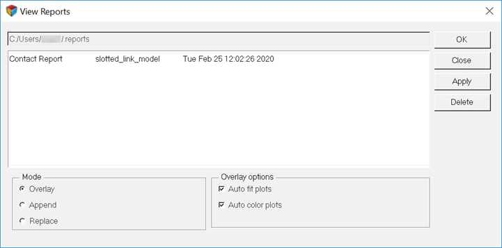
- Post-process the results using a report generated automatically.
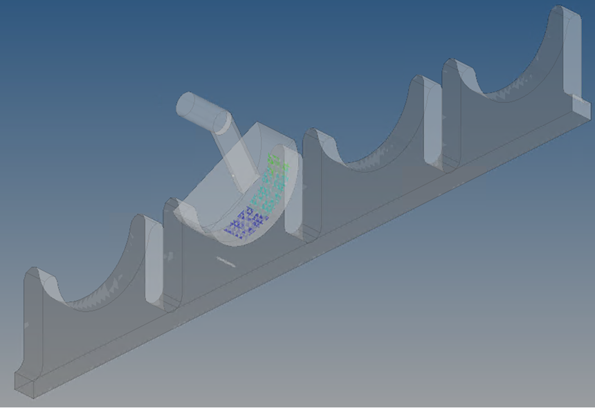
For this tutorial, you will use a slotted link model.
For this type of meshed representation of 3D rigid bodies, MotionSolve uses a numerical collision engine that detects penetration between two or more surface meshes and subsequently calculates the penetration depth(s) and the contact force(s).
There are numerous 3D contact applications (gears, cams, mechanisms with parts in contact, and so on) that may be solved using this approach.
Slotted Link Model
A slotted link mechanism (sometimes also referred to as a scotch-yoke mechanism) is a type of mechanism used to convert an input rotational motion into continuous or intermittent translational motion of a sliding link or yoke part. The motion is transferred via a contact force between parts of the mechanism that are in contact. Both normal and friction contact force may be responsible for the transfer of motion.
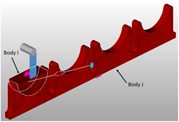
Such mechanisms find common application in valve actuators, air compressors, certain reciprocating and rotary engines, among others. The figure below illustrates a slotted link mechanism that will be modeled in this tutorial.
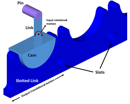
Figure 1. A Slotted Link Mechanism. The cam is in contact with the slotted link as shown, whereas the pin comes into contact with the slots.
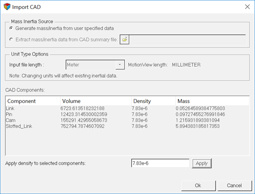
Import CAD Geometry into MotionView
Create Joints and Motion
At this stage, the model contains the following bodies along with their associated graphics:
| Entity name | Entity type | Description |
|---|---|---|
| Slotted_Link | Rigid Body | The slotted link body. |
| Cam | Rigid Body | The cam body. |
| Pin | Rigid Body | The pin body. Together the cam and the pin bodies engage the slotted link. |
| Link | Rigid Body | A connector body between the pin and the cam. |
| Slotted_Link | Graphic | The graphic that represents the slotted link body. This is a tessellated graphic. |
| Cam | Graphic | The graphic that represents the cam body. This is a tessellated graphic. |
| Pin | Graphic | The graphic that represents the pin body. This is a tessellated graphic. |
| Link | Graphic | The graphics that represent the link body. This is a tessellated graphic. |
The Pin, Link, and Cam bodies are fixed to each other and pivoted to the Ground Body at the Cam center. The Slotted_Link can translate with respect to the Ground Body.
Define Contact Between the Colliding Geometries
- Cam and the Slotted_Link
- Pin and the Slotted_Link
Set Up a Transient Simulation and Run the Model
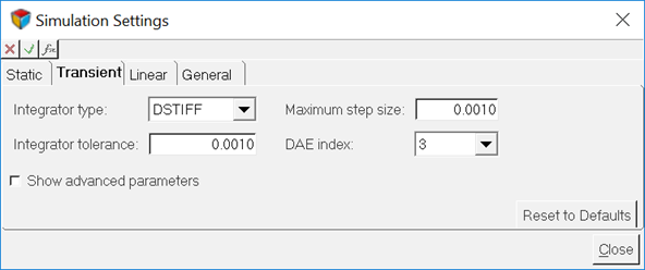
At this point, you are ready to set up a transient analysis for this model.
Post-process the Results

Figure 18. Contact Overview Table
Visualize the Contact Forces via H3D
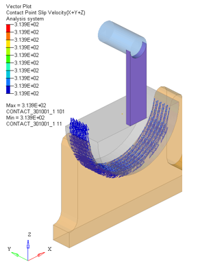
The first HyperView page (second in the session) displays a vector animation of contact force aggregated over the contact region. You may hide one or more parts to view this clearly in the modeling window. This is illustrated in the figure below.
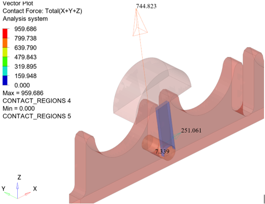
Figure 21. The contact force vector at the contacting regions
Contact Summary
Use the Page Navigation icon, ![]() , to navigate to the next page.
, to navigate to the next page.
The third page in the session can be used to get an overall summary of the contact simulation. This page contains table that tabulates the summary, as well as a HyperView window that displays the penetration for the entire simulation. The table provides a summary of the maximum penetration depth and maximum force. This page provides a bird’s eye view of the contact phenomenon happening within the model. The contour of penetration depth is a static image that highlights all regions that come under contact during the entire period of the simulation.
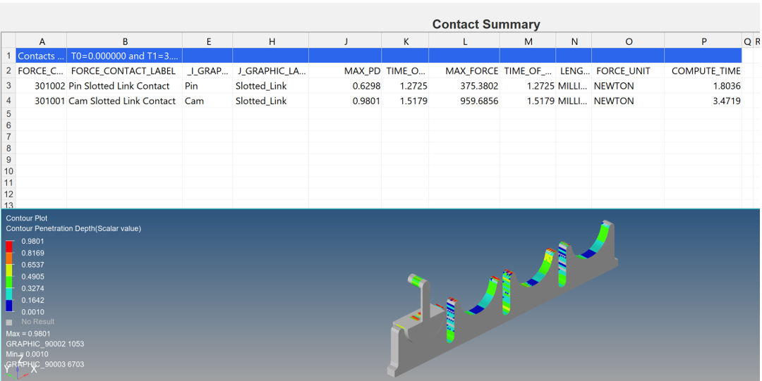
Figure 22. Contact summary page
Visualize the Penetration Depth via H3D
Navigate to the next page.
The fourth page in the session can be used to visualize the penetration depth over the course of the simulation.
Visualize MotionSolve Outputs
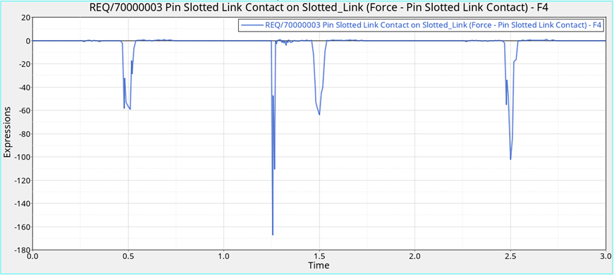
Plot the Contact Forces via ABF
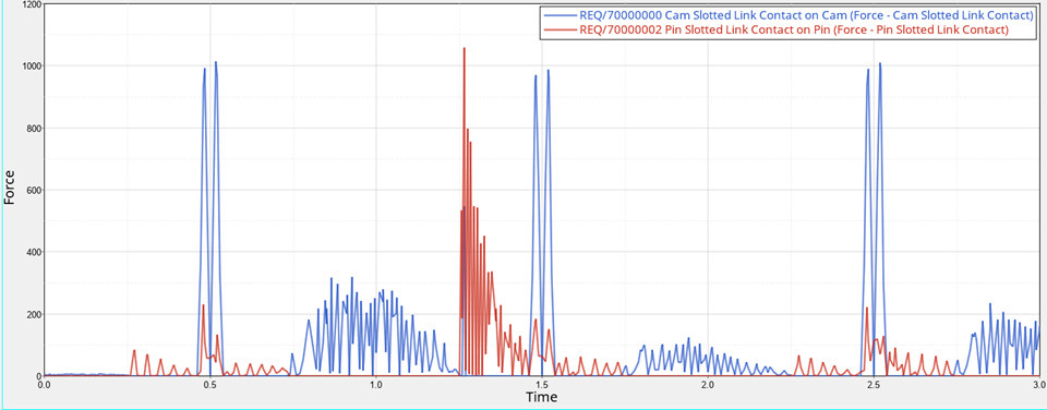
Figure 27. Total Contact Force Magnitude
Manually Plot Other Output Requests
Summary
In this tutorial, you learned how to create a well-meshed representation from CAD geometry. Further, you learned how to set up contact between meshed geometries. Also, you were able to inspect the geometry to make sure the surface normals were correct and there were no open edges or T connections.
You were also able to setup a transient analysis to calculate the contact forces between these geometries and post-process the results via vector and contour plots, in addition to plotting the contact force requests.
