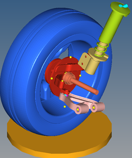
MV-1035: Import CAD or FE into MotionView
- Import a CAD assembly into MotionView using HyperMesh.
- Import a CSV file to create Points
- Create an MBD model using the imported data.
The Import CAD or FE utility in MotionView allows you to import CAD or FE assemblies. CAD formats include CATIA, Parasolid, Pro E, STEP, JT, SolidWorks and Unigraphics. FE formats include HyperMesh, OptiStruct, and Nastran.
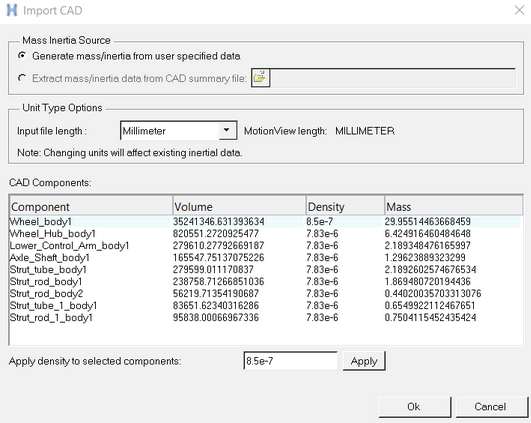
CAD or FE assemblies can be imported into MotionView as graphics only to be associated with existing bodies, or as new bodies with calculated mass and inertia properties along with graphics.
- Component Mass
- Component Moments of Inertia
- Component Center of Gravity Location
- Component Graphics
The CAD import utility calls HyperMesh in the background to write out a graphic file (*.h3d) which holds the geometry information in a tessellated form. While importing CAD or FE to create new bodies with mass and inertia, the utility uses HyperMesh to calculate mass, inertia and CG location.
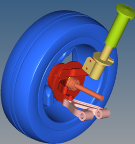
In the following exercise, you will import a CAD assembly into MotionView, simplify the model from a multibody analysis point of view, and define constraints, model inputs and model outputs.
Please copy all of the files from the mbd_modeling\automation\CAD folder into your <working directory>.
Load a CAD File in MotionView
In this step, the focus is on understanding the process of import and model simplification.
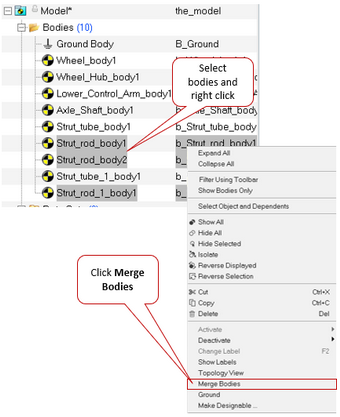
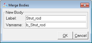
Consolidate and Rename the Suspension Assembly Bodies
- Mass and inertia of the newly created body upon Merge will be equal to the effective mass and inertias of the bodies being merged.
- A new CG point is created at the effective CG location of the bodies being merged.
- Pair bodies cannot be merged.
- The Merge option works only within same container (System/Assembly/Analysis). Merging bodies which belong to different container entities is not supported. The context menu item will not appear in these cases.
- If the bodies that are being merged are referred to in expressions, post Merge these expressions need to be corrected to point to the newly created body.
- Graphics that belong to bodies being merged are automatically resolved to the new body.
- Joints, bushings etc. that are associated with the bodies being merged if any, are automatically resolved to the new body.
Create Points
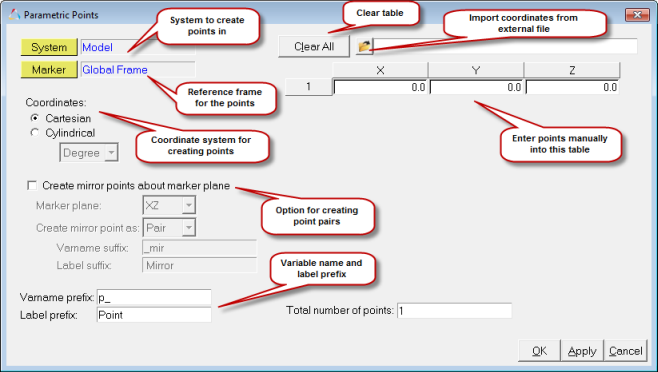
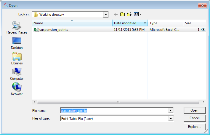
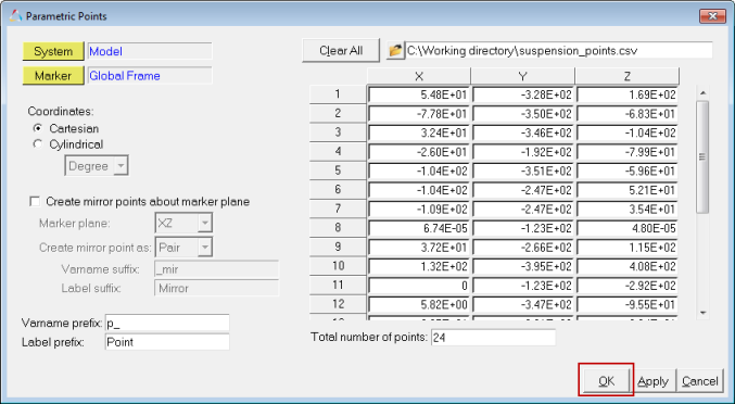
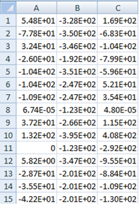
After creating the bodies, additional points are needed that will be used to specify joint locations and joint orientations. These points can be created using the macros available in the Macros menu.
Create Joints and Spring Damper
In this step, you will add the joints to connect the bodies and a spring damper between Strut tube and Strut rod.
Add a Jack to the Model
Specify Motion Inputs and Run the Model in MotionSolve
In this step, you will create a motion that is applied to the jack and solve the model.


