Project tools onto targets in a specified direction and split the targets. You can
also extract the projection without splitting the targets to create wire
geometry.
On the Geometry ribbon, select the
Project & Split tool.
Note: The tool may be hidden in a dropdown menu. To access
the dropdown menu, you can do one of the following:
Click and hold the currently displayed tool (Slice or
Intersect).
Select at the lower right corner of the
currently displayed tool (Slice or Intersect).
The guide panel appears.
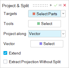
Designate the Targets:
If you select...
Then do this
Select Target Parts
(default)
Select one or more target parts to split. To deselect,
hold down Ctrl while
clicking.
Select Target Surfaces
Select one or more target surfaces to split.
Designate the Tools:
Click the Select Tools button.
Select one or more sketches, edges, faces, or surfaces.
Designate a direction to Project along:
Normal: Project the tools along the normal
direction.
X: Project the tools along the global
x-axis.
Y: Project the tools along the global
y-axis.
Z: Project the tools along the global
x-axis.
Vector: Project the tools along a selected
vector, which can be a linear edge or an axis.
Shortest Distance: Project the tools along the
direction that minimizes the distance between the tools and
targets.
Surface
Normal: Project the tools along the normal of a selected
planar face. If you select this option, next to Surface
Normal, click the Select button. Then
select a planar face to project the tools along the normal of the selected
planar face.
Configure the following options:
Extend: Extend the tools to completely cut the
targets.
Extract Projection Without Split: Extract the
projection without splitting the targets to create wire geometry for surface
modeling.
Click Apply.
Right-click and mouse through the check mark to exit, or double-right-click.

 at the lower right corner of the
currently displayed tool (Slice or Intersect).
at the lower right corner of the
currently displayed tool (Slice or Intersect).