High Pressure Process
Define the parameters for a high pressure die casting process.
Location: High Pressure is an option on the Basic Setup icon on the Casting ribbon.

High pressure die casting uses a machine to inject molten metal into permanent metal dies under high pressure. It is a good technique for manufacturing complex parts with a high degree of accuracy, particularly lightweight parts with thin walls that require consistent dimensions. The high pressure is needed to fill the mold completely and avoid solidification during the casting process.
High pressure die casting uses two distinct velocities. The molten metal is first pushed at a low velocity (initial velocity) in order to avoid turbulence and the formation of bubbles. Just before the material enters the mold, the velocity increases (second phase velocity), and the molten metal is injected very quickly into the die assembly to fill it completely.

Define High Pressure Parameters
High Pressure Options
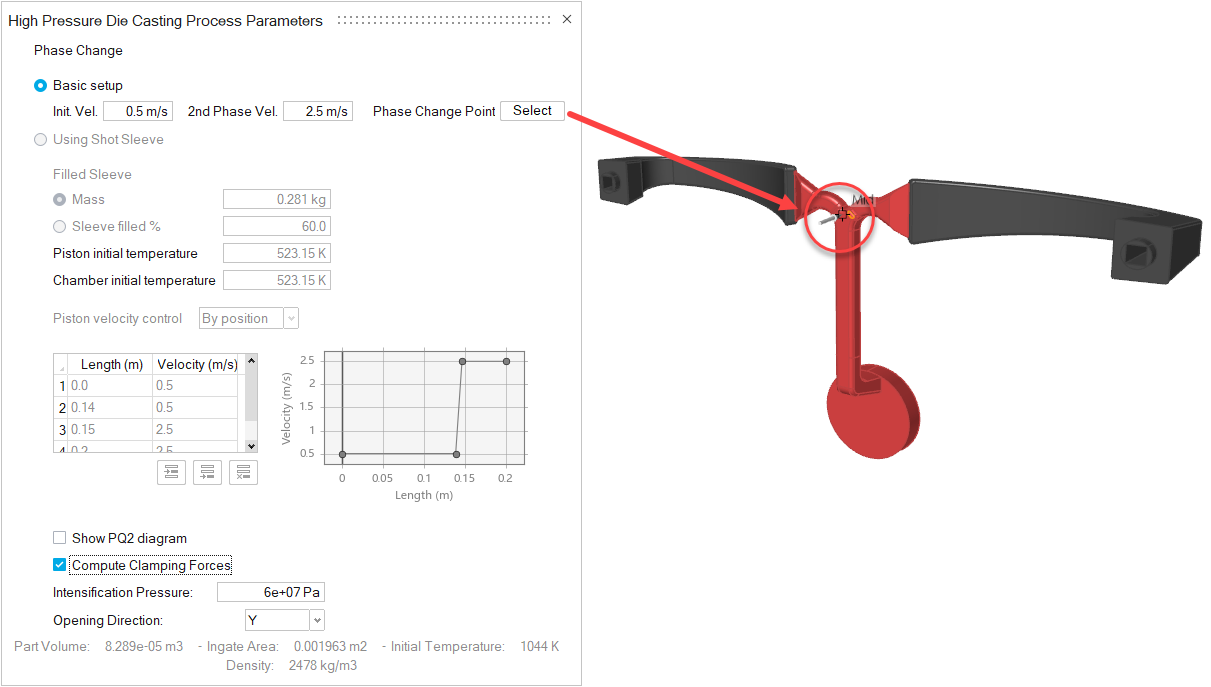
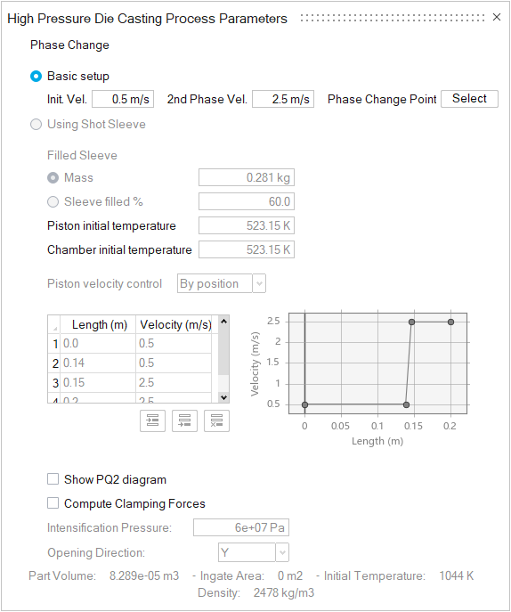
- Basic setup
- This option will be selected when no shot sleeve is included in the model.
- Initial Velocity (m/s)
- Typical values for Initial Velocity are 0.2–0.5 m/s.
- Second Phase Velocity (m/s)
- Typical values for Second Phase Velocity are 2.0–5.0 m/s.
- Phase Change Point
- To specify where the initial velocity changes to the second
phase velocity, click Select, and
then click a point on the runner.Tip: The phase change point needs to be on the runner, before the material enters the mold.

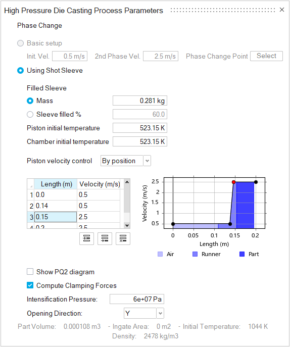
- Using Shot Sleeve
- This option will be selected when a shot sleeve is present in the model.
- Filled Sleeve
- Select Mass to define the quantity of
metal introduced in the piston shot sleeve in kg or
Sleeve filled % to enter the
percentage that the piston shot is filled after pouring the
liquid in.Note: By default Mass will be automatically computed as the volume of the selected part plus the runner.
- Piston Velocity Control
- Select By position or By
time, and define the piston velocity
profile.
By position allows you to select the first and second velocity when the liquid reaches a selected position on the shot sleeve. The final position will be automatically edited depending on the designed shot sleeve length.
By time allows you to select the first and second piston velocity with respect to the filling time.
You can enter values in the table or edit the points on the graph. Click to
add a new row after a selected data point, add a new row
after the last data point, or delete a selected row.
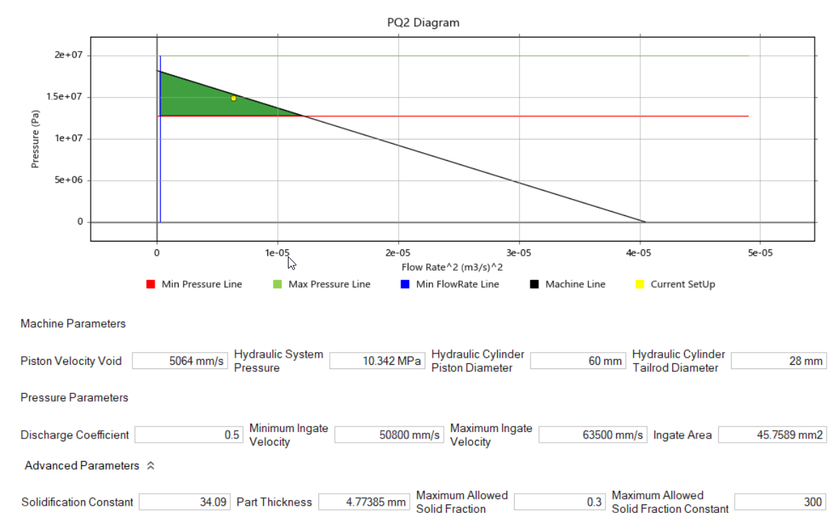
- PQ2 Diagram
- Enable the Show PQ2 diagram option to
reveal this tool. It can help you improve the machine setup
in the high-pressure die casting process. The diagram shows
a green safety region on a pressure vs flow rate graph. The
safety area is defined by the minimum and maximum pressure
and minimum and maximum flow rate during the casting
process. Note: The PQ2 diagram and its parameters are useful only when the model includes a shot sleeve.

The yellow Current Setup point in the diagram shows the current machine setup based on the settings in the Piston Velocity and Ingate Area fields.
- Compute Clamping Forces
- Enable this option to have the solver calculate the force necessary to keep the mold closed during casting. Clamping force is the product of the separation force for the mold and a user-editable safety factor. View the result and edit the safety factor in the Analysis Explorer.
- Intensification Pressure
- This is the maximum pressure applied during the casting process. The value defaults to 600 Kg/cm2 (or 60 MPa). This field is editable when Compute Clamping Forces is enabled.
- Opening Direction
- This is the axis along which the mold will open. The solver uses this information when determining the clamping force.
 next to the
Basic Setup icon, then select
