Freehand Panel
Use the Freehand panel to morph your mesh without needing domains, handles, or morph volumes.
Location: Tools page > HyperMorph module
Separate options exist for moving selected nodes directly, recording actions made in other panels, "sculpting" meshes with different virtual tools, and saving a morph as a shape.
Changes made on one subpanel do not affect the others, and are persistent so that you can switch freely between subpanels without losing any settings already made.
Sculpting Subpanel
Use the Sculpting subpanel to mold a mesh with a variety of virtual tools, such as creating hemispherical divots, cone-shaped projections, or molding sections with feature lines.
Areas of the mesh can be pushed or pulled to reshape it, creating either indentations or projections on the mesh.
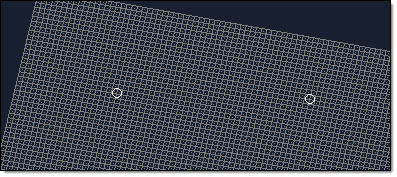
Figure 1. Two Nodes Selected, Tool not Applied
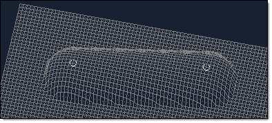
Figure 2. Ball Tool Applied to the Mesh. The ball tool has been applied to the mesh as if it had been rolled from one node to the other.
| Option | Action |
|---|---|
| affected elements | Select the elements you wish to be subject to the sculpting. In this way, you can preserve parts of the mesh during sculpting (by simply not picking them). |
| angle = | When sculpting with the cone tool, specify the angle of the cone's taper. |
| base | The base node serves
as a "handle" for the tool. The base node is moved along the
path and the tool moves relative to the base
node. Note: Available for node list, line, surface, or
mesh.
|
| mesh compression |
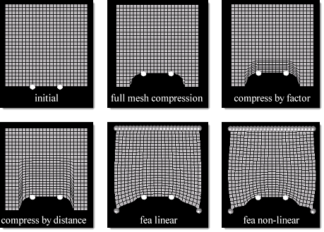 Figure 3. |
| move direction | Define the direction that nodes are moved when sculpted. The two options are to use a standard plane and vector selector to define a vector, or to sculpt in the mesh element's normal direction. |
| offset = | Specify the offset to determine how far the tool will be offset from the path in the move direction. |
| options | Opens the Morph Options panel. |
| radius = | When sculpting with the ball or cylinder tool, specify the size of the tool. |
| sculpting tool | Choose the basic shape
that will be used for sculpting. When sculpting with a cylinder or plane, a new (unlabeled) plane and vector selector displays under the tool label. Use this (including a base node) to define the cylinder's axis, or the plane tool itself. 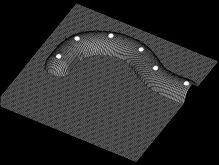 Figure 4. Ball. The ball tool has been applied to a node list. 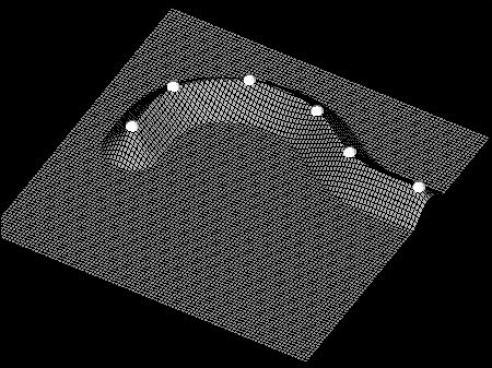 Figure 5. Cone. The cone tool has been applied to a node list with an offset. The tip of the cone is moved along the node list, which, if the node list was selected along the mesh to be sculpted, will not result in any morphing. Use an offset to push the cone past the surface of the mesh as shown in the example. 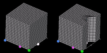 Figure 6. Cylinder. A cube has been sculpted with a cylinder tool at a single point. Notice the mesh compression extending into the body of the mesh 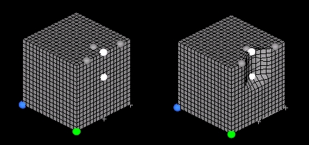 Figure 7. Node List. A cube has been sculpting with a node list (gray circles) along a path (white circles). 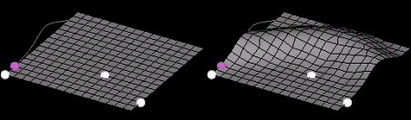 Figure 8. Line. A line tool is used to sculpt a mesh. Notice how the base point (purple circle) is used to locate the line relative to the path (white circles). 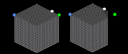 Figure 9. Plane. A plane tool is used to sculpt a solid cube. A single node is used for the path and mesh compression of 0.5 is selected. Notice that the sculpt direction is different from the plane normal. 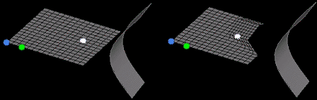 Figure 10. Surface. A surface is used to sculpt a mesh. A single node is used for the path (which ends up getting morphed due to the mesh compression). Notice the effect of the taper angle (45 degrees) on either side of the tool and how it prevents large mesh distortions at the tool edge. 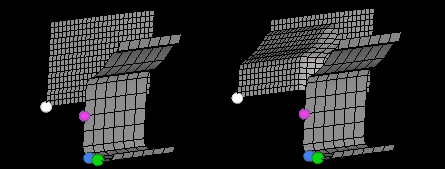 Figure 11. Mesh. A mesh tool is used to sculpt another mesh. Since the path lies on the target mesh and the base node is at the leading face of the tool, an offset was used to create the sculpting. |
| taper angle = | When sculpting with a
node list, line, surface, or mesh tool, specify a taper angle
for the tool to alter the taper of the resulting deformation.
The taper of the tool is like a shroud around the tool extending opposite of the sculpt direction, at the given angle. For instance, the taper for a point is a cone. The taper helps to smooth transitions between sculpted and non-sculpted regions. |
| tool path | Choose the path along
which the tool will be moved; the center of the tool follows the
path.
|
Command Buttons
| Button | Action |
|---|---|
| finish | Stop morphing macro recording. |
| morph | Perform the morphing (move nodes). |
| move + | Sculpt in the positive
direction relative to the move direction input.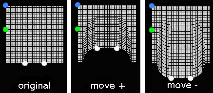 Figure 12. |
| move - | Sculpt in the negative direction relative to the move direction input. |
| redo | Redo the last morphing action. |
| redo all | Redo all recent morphing actions. |
| save | Save the current shape. |
| start | Begin recording a complex morph macro. |
| undo | Undo the last morphing action. |
| undo all | Undo all recent morphing actions. |