Browsers supply a great deal of view-related functionality by listing the parts of a model in a tabular and/or tree-based
format, and providing controls inside the table that allow you to alter the display of model parts.
FE geometry is topology on top of mesh, meaning CAD and mesh exist as a single entity. The purpose of FE geometry
is to add vertices, edges, surfaces, and solids on FE models which have no CAD geometry.
Manage all of the IDs for the entities that you create, and define ID ranges for all of the entities in each Include
file in relation to the full model in order to avoid ID duplication.
Perform automatic checks on CAD models, and identify potential issues with geometry that may slow down the meshing
process using the Verification and Comparison tools.
Local coordinate systems can be used for setting up loads/boundary conditions that do not act in the global axis direction,
transforming results, defining material orientation, and many other operations.
Use the Auto Contacts tool to determine contact interfaces between selections of components or elements. Based on
the user-specified options like proximity tolerance, surface creation method, main surface type, and secondary type,
the tool generates contacts based on set segments or node and element combinations.
Tools and workflows that are dedicated to rapidly creating new parts for specific use cases, or amending existing
parts. The current capabilities are focused on stiffening parts.
Perform automatic checks on CAD models, and identify potential issues with geometry that may slow down the meshing
process using the Verification and Comparison tools.
Review the selected Part Assembly/Part in HyperWorks
graphics.
This review function uses parallel processing and is used in case of huge number of
selected part and it takes time in normal import operation.
Once the model is displayed in the graphics, you can select unwanted parts in the
graphics and delete them; simultaneously, the Part Browser gets
updated.
Note: The number CPU set in the configuration general section is used
for parallel processing.
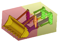
It is recommended to use this function before CAD Intersection or Comparison is
executed for full car model where it is not sure the parts are in right
position. Figure 1. Intersection Check on Each CPU
Right-click in the Verification/Comparison Browser and select Review
Results from the context menu.