Verification Manual
Verifies the validity of the journal bearing elements provided in Bearings - Journal.
Introduction
Two implementations of MotionSolve’s journal bearings, a Dynamic Gumbel Long Aligned Journal Bearing and a Gumbel Short Misaligned Journal Bearing, are verified by comparing their behavior against data found in 1 and 2. The purpose of the verification is to establish the truth, accuracy, and validity of the journal bearing elements in MotionSolve.
Test Subject - Aligned Journal Bearing
| Dynamic Gumbel Long - Aligned Journal Bearing | ||
|---|---|---|
| Parameter | Value | Units |
| Bearing Radius | 10 | mm |
| Journal Radius | 9.8 | mm |
| Journal Bearing Width | 40 | mm |
| Lubricant Dyn. Viscosity | 0.4*1e-6 | Ns/(mm^2) |
| method | Dynamic Gumbel Long | - |
| Internal connection type | PLANAR | - |
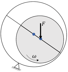
Figure 1. Schematic Diagram of the Aligned Journal Bearing
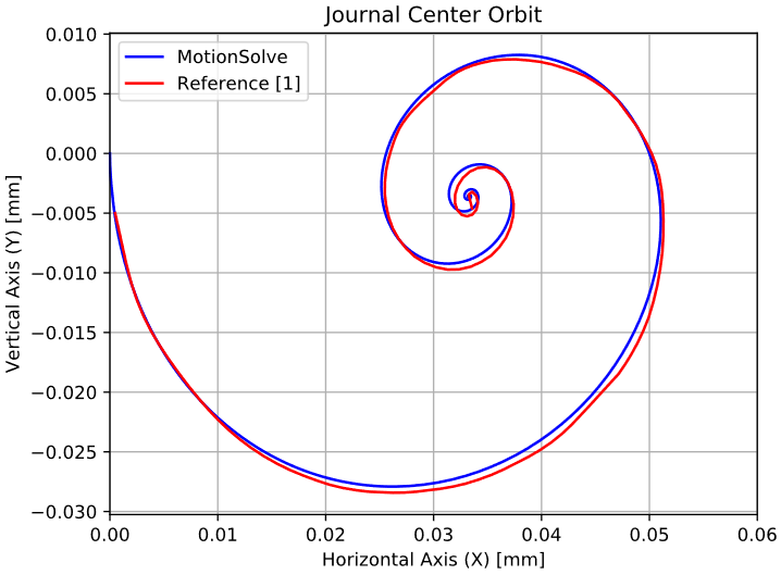
Figure 2. Diagram 1 - Journal Center Orbit
There is a very good correlation between MotionSolve and the curves provided by 1. Due to the constant external load, the journal follows a spiral orbit until it reaches a steady state.
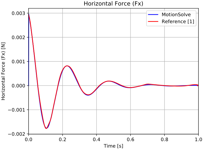
Figure 3. Diagram 2 - Horizontal Lubrication Force (Fx)
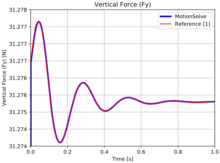
Figure 4. Diagram 3 - Vertical Lubrication Force (Fy)
Those oscillating forces decay with time due to the damping characteristics of the fluid until they reach steady value. In this steady state condition, the horizontal force is zero since no external load in the horizontal direction is applied, while the vertical force is the sum of the journal weight and the external load.
Test Subject - Misaligned Journal Bearing
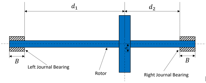
Figure 5. Schematic Diagram of the Unbalanced Rotor
| Rotor Parameters | ||
|---|---|---|
| Parameter | Value | Units |
| mass | 1 | kg |
| [Ixx, Iyy, Izz] | [1e4, 1e4, 3e5] | Kg*mm^2 |
| e | 1 | mm |
| d1 | 200 | mm |
| d2 | 100 | mm |
| ω | 100 | rad/s |
| Left Misaligned Journal Bearing Parameters | ||
|---|---|---|
| Parameter | Value | Units |
| Bearing Radius | 20.3 | mm |
| Journal Radius | 20 | mm |
| Journal Bearing Width (B) | 20 | mm |
| Lubricant Dyn. Viscosity | 0.0242*1e-6 | Ns/(mm^2) |
| method | Gumbel Short | - |
| Internal connection type | NONE | - |
| Right Misaligned Journal Bearing Parameters | ||
|---|---|---|
| Parameter | Value | Units |
| Bearing Radius | 20.3 | mm |
| Journal Radius | 20 | mm |
| Journal Bearing Width (B) | 20 | mm |
| Lubricant Dyn. Viscosity | 0.0242*1e-6 | Kg/(mm*s) |
| method | Gumbel Short | - |
| Internal connection type | INPLANE | - |
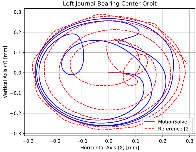
Figure 6. Diagram 4 - Left Journal Bearing Center Orbit
The comparison does not show any similarities between MotionSolve and 2 during the initial transient phase, but converges to a good correlation once steady state is achieved. In steady state, the two orbits are very similar.
In contrast to ideal rigid bearings (for example, a revolute joint), journal bearings provoke an elliptical orbit since they act more like spring-dampers than a perfect joint. Thus, the dynamics of the system are more complicated.
Time histograms of lubrication forces cannot be compared due to the lack of such data in 2.
Conclusion
Comparisons of MotionSolve journal bearing models against literature models were conducted. The comparison was first performed on a Dynamic Gumbel Long Aligned Journal Bearing, followed by a Gumbel Short Misaligned Journal Bearing. In the simple aligned journal bearing model, the correlation between the models is almost perfect. Only very small deviations exist. In the more complicated model of the rotor, good correlation is approached at steady state. The verification was performed only on two types of journal bearings, while the library includes more of them. The remaining journal bearing types use the same principles and a similar outcome as shown here can be expected.
References
- P. Flores, J. Ambrosio, J.C.P. Claro, H.M. Lankarani, C.S Koshy, "Lubricated revolute joints in rigid multibody systems", Nonlinear Dyn (2009) 56 277-295, DOI 10.1007/s11071-008-9399-2.
- R. Stefanelli, P.P. Valentini, L. Vita, "Modelling of Hydrodynamic Journal Bearing in Spatial Multibody Systems", IDETC/CIE, 2005.