Advice of utilization / limitations
Introduction
This section reviews several informational elements on the utilization conditions of cuts and deals with the current limitations of the software in this respect.
It specifically answers the question: where should the cuts be located?
When should the cuts be located?
It is necessary to create the cuts whenever there is a connectivity problem, taking into account the following elements…
- it is not necessary to create a cut as the group of non connected region (with holes) is already cut by «replacing elements» (plan of symmetry/periodicity, surface region…). The «replacing elements» are presented in the section below
- it is necessary to take into account the current limitations of the software (what is authorized and what is not)
«replacing elements»
The cuts are not necessary when there are «replacing elements» that play the role of cut. These elements are presented in the tables below.
For an electric loop
- a symmetry plane of the tangent magnetic field type (which means a normal electric field)
- a periodicity plan
These elements are identified by the command “Check Physics”
Limitations in terms of construction
A cut should not be in contact with:
- a plane of periodicity / symmetry
- a face region
- the boundary between two mechanical sets: sliding surface or dissociation surface
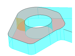
In this example, the cut on the mesh in the thickness of the device (in transparent yellow) is in contact with the surface region (parasite air gap) at the top part of the device (in transparent red)
Limitations in terms of functioning
It is not possible to solve a geometric parametric scenario when the project contains cuts of type cut on the mesh (because of the deletion / re-generation of the mesh at each time step).