Initialization by FE solution: examples
Example 1 : presentation
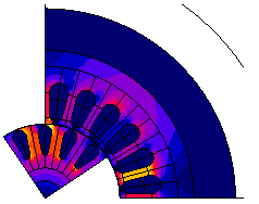
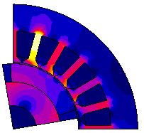
The studied device is an asynchronous motor.
Computation conditions:
A first Steady State AC Magnetic computation for the slip value of 6 % is carried out. It permits to establish the corresponding steady state regime of the device. It also permits to the have the steady state field of the current density in the rotor bars.
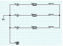
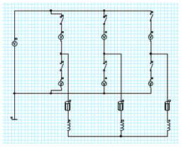
| Domain finite elements | Electrical circuit |
|---|---|
|
|
Example 1: results
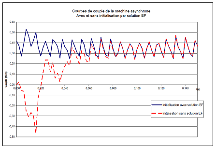
The curve of the time variation of the electromagnetic torque of the asynchronous machine is represented in the figure below in the two following conditions: with or without initialization by a FE solution.
Main results:
-
without initialization by a FE solution (dotted lines): one can note a transient period before the curve reaches the steady state regime
-
with initialization by a FE solution (solid lines): the curve reaches the steady state regime faster
Example 2 : presentation
The studied device is a synchronous motor with permanent magnet.
Computation conditions: A first TM computation is made, simulating the increase of the machine speed to the rated point (nnom = 1000 rpm). The second computation, initialized by the FE solutions of the first one goes back to the steady state regime.
| Domain finite elements | Electrical circuit |
|---|---|
|
|
Example 1 : results
The curve synchronous machine speed increase is represented below.
A first phase consists in reaching the rated speed 1000 rpm. The second problem considers the results of the first phase at the time t = 0.03 s.
