Fully automatic meshing or mixed meshing: comparison
Introduction
Two mesh strategies are proposed:
- mesh the whole of the domain with one mesh generator: the automatic mesh generator
- carry out a meshing by subdomains (mixed meshing), by using, for each domain, the mesh generator that is the best adapted to the physical phenomena to be modelled
This choice is made from case to case, and it depends on the constraints connected to the modelled device.
Managing the constraints
The meshing operation must observe a certain number of constraints connected with the modelled device.
| Constraint | Description of the constraint | Managed by |
|---|---|---|
| Geometrical | To respect the geometry of the device (interfaces between different volumes) | The software |
| Physical | To adapt the model to the physics of the problem (thin air-gap, skin depth) | The user |
Automatic mesh
For an automatic mesh, the software completely ensures that the geometrical interfaces are respected.
To accomplish this, the algorithm of the automatic mesh generator inserts additional nodes on the faces or inside the volumes, so as to respect the node density information assigned to the points and lines.
Mixed mesh
With a mixed mesh, the user has more options to adapt the mesh to the physics of the problem.
On the other hand, they can face certain limitations of the software (in 3D) ; the conformity of the meshing at the level of the geometric interfaces can sometimes be difficult to carry out by the software.
Mixed mesh: examples of use
When modeling electrotechnical devices, mesh the air and volumes with complex topology with the automatic mesh generator, while the more sensitive parts (magnetic circuit, air-gap, skin depth, etc.) are generally meshed with the mapped or the extrusive mesh generator.
When modeling rotating machines, it is advisable to generate an identical mesh on the faces (slots of machines, etc.), with the linked mesh generator.
Constraint of mesh conformity
The mesh must conform , i.e. there must be a “continuity” or matching of elements on the interfaces between different domains.
If it is common to mix triangular and rectangular elements in 2D, mixing hexahedral and tetrahedral elements in 3D can pose certain problems.
In 3D, the conformity with the interface between the meshed domains with hexahedrons or prisms, and the meshed domains with tetrahedrons is ensured by the automatic insertion of pyramid elements .
An example is represented in the figure below.
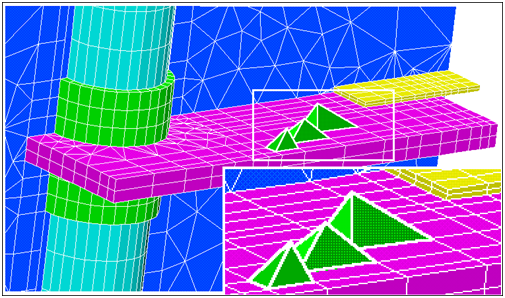
Example of non-conformity
An example of non-conformity on the interface between two domains is shown below. The first is meshed with hexaedrons and the second volume is meshed with tetrahedrons.
Two triangular surface elements consisting of faces with two tetrahedral elements, correspond to a rectangular surface element that is a face of a hexahedron

This situation appears when a mapped meshed volume is in contact with a linked meshed volume. The non conformity is forbidden in Flux
Algorithm for repairs of non-conformities
To ensure conformity of the mesh, Flux uses an algorithm to repair non-conformities between hexahedrons and tetrahedrons or between rectangular fa prism faces and tetrahedrons by inserting pyramids.
In the presence of triangular and rectangular surface elements, Flux generates pyramids, starting with two triangular elements.
Two cases may occur:
- The two tetrahedrons attached to the two triangular surface elements have the same vertex node. In this case, the tetrahedrons can be connected to create a pyramid.
- If the two tetrahedrons do not have the same vertex node, Flux will insert a new node in an appropriate position.

The insertion of pyramids is not always possible, and there are a certain number of limitations to the algorithm when repairing non-conformities.
First limitation
If the rectangular mesh is very distorted, the triangular elements belonging to tetrahedrons may cut the rectangular elements. This case is illustrated in the figure below.

In this case, Flux cannot ensure the mesh conformity. This mesh will fail.
Second limitation
The second limitation is less clear. To ensure the conformity of the mesh by inserting pyramids, Flux adds a certain number of nodes. However, this algorithm does not work properly in the presence of sharp angles. This limitation is illustrated by the example below.
A simple device consisting of 3 hexahedral volumes is shown in the following figure:
- two external volumes are meshed using the mapped mesh generator
- the inner volume is meshed using the automatic mesh generator
The failure of the non-conformity repairing algorithm is due to the fact that the insertion of nodes to construct pyramids is not possible for this configuration.

Use
By experience we realize that the pyramid generation algorithm is more robust when the elements meshed with the automatic mesh generator are bigger than the elements meshed mapped or extrusive mesh generator.
In some cases, the volume meshing based on the advancing front method can be a solution in order to favor the creation of nodes and to permit the insertion of pyramids, (see Meshing of volumes algorithms ).