Turbulent Flow Over a Backward-Facing Step
In this application, AcuSolve is used to simulate fully developed turbulent flow over a backward-facing step. AcuSolve results are compared with experimental results as described in Driver (1985) and on the NASA Langley Research Center Turbulence Modeling Resource web page. The close agreement of AcuSolve results with experimental data and reference turbulence model performance validates the ability of AcuSolve to model cases with turbulent flow that forms a shear layer, recirculates and then reattaches downstream of the divergent step.
Problem Description
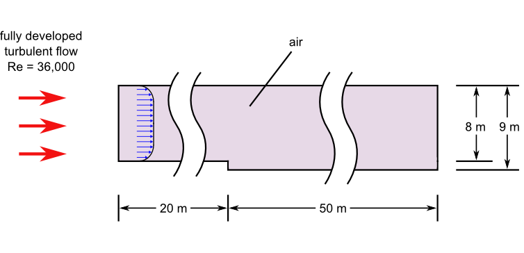
Figure 1. Critical Dimensions and Parameters for Simulating Turbulent Flow Through a Channel with a Backward-Facing Step
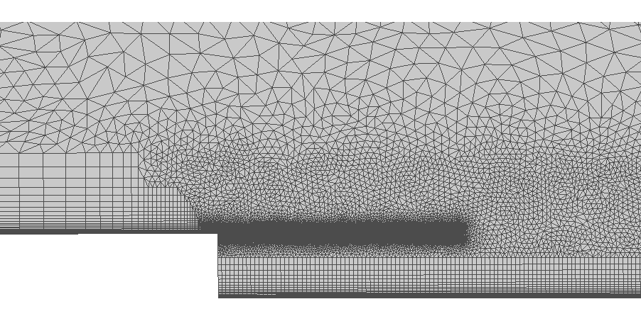
Figure 2. Detail of Mesh Near the Backward-Facing Step
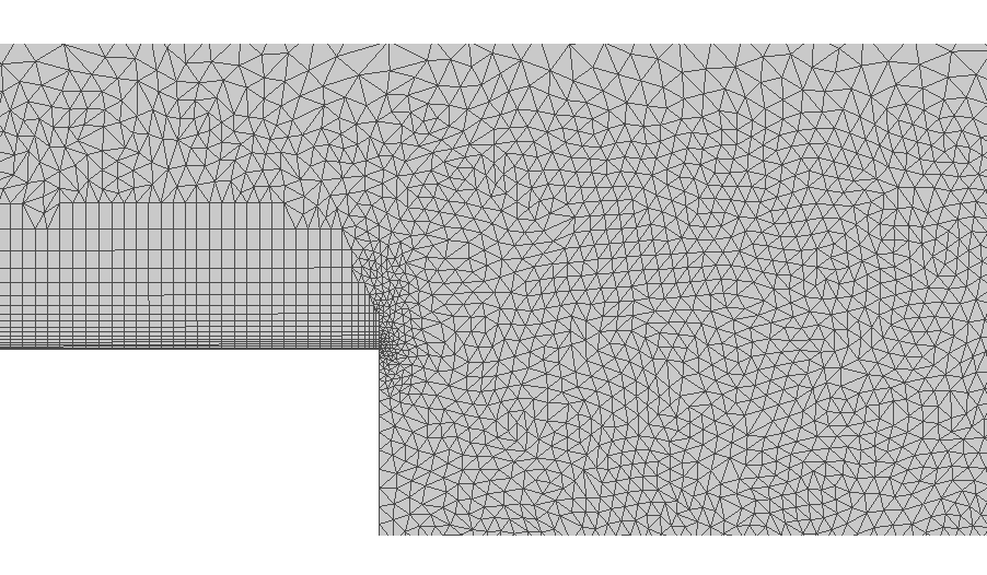
Figure 3. Finer Detail of Mesh Near the Backward-Facing Step
AcuSolve Results
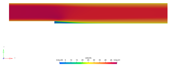
Figure 4. Velocity Contours Showing Low Velocity Near the Step Wall
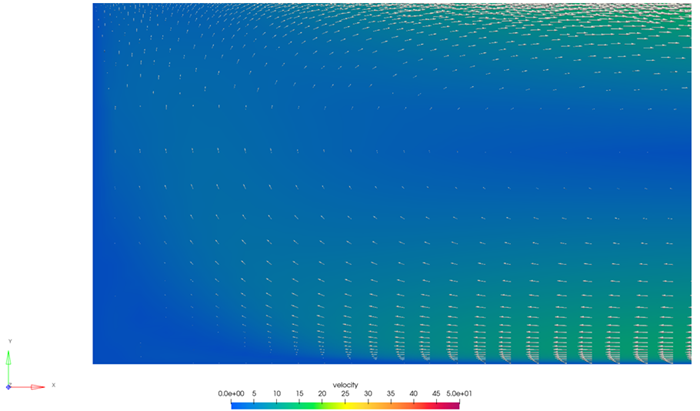
Figure 5. Close-Up View of Velocity Vectors and Contours in the Cross-Stream Plane Directly After the Step
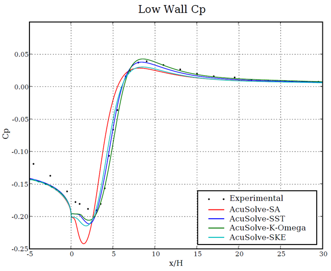
Figure 6. Coefficient of Pressure Plotted Against Location Along the Lower Wall Before and After the Step
Summary
In this application, a fully developed turbulent flow at a Reynolds number of 36,000 is studied and compared against experimental data. The AcuSolve results compare well with the experimental data for pressure coefficient. The performance of the Spalart Allmaras turbulence model was found to be consistent with previously published results for flow over a backward facing step (NASA 2015). The K-ω model appears to perform the best out of the three, predicting the reattachment and pressure distribution most accurately. AcuSolve demonstrates the ability to predict the shear layer in this type of application, the recirculation that occurs downstream of the step, as well as the reattachment point within the channel.
Simulation Settings for Turbulent Flow over a Backward-Facing Step
HyperWorks CFD database file: <your working directory>\backstep_turbulent\backstep_turbulent.hm
Global
- Problem Description
- Analysis type - Steady State
- Turbulence equation - Shear Stress Transport
- Auto Solution Strategy
- Max time steps - 100
- Relaxation Factor - 0.5
- Material Model
- Air
- Density - 1.183 kg/m3
- Viscosity - 1.4575e-3 kg/m-sec
Model
- Air
- Volume
- Fluid
- Element Set
- Material model - Air
- Element Set
- Fluid
- Surfaces
- +Z
- Simple Boundary Condition
- Type - Slip
- Simple Boundary Condition
- -Z
- Simple Boundary Condition
- Type - Slip
- Simple Boundary Condition
- Inlet
- Simple Boundary Condition - (disabled to allow for nodal boundary conditions to be set)
- Advanced Options
- Nodal Boundary Conditions
- X-Velocity
- Type - Linear
- Precedence - Always
- Curve fit variable - Y reference coordinate
- Curve fit values - (included in database)
- Y-Velocity
- Type - Linear
- Precedence - Always
- Curve fit variable - Y reference coordinate
- Curve fit values - (included in database)
- Z-Velocity
- Type - Zero
- Kinetic Energy
- Type - Linear
- Precedence - Always
- Curve fit variable - Y reference coordinate
- Curve fit values - (included in database)
- Eddy Frequency
- Type - Linear
- Precedence - Always
- Curve fit variable - Y reference coordinate
- Curve fit values - (included in database)
- X-Velocity
- Nodal Boundary Conditions
- Outlet
- Simple Boundary Condition
- Type - Outflow
- Simple Boundary Condition
- Wall - Lower - Downstream
- Simple Boundary Condition
- Type - Wall
- Turbulence wall type - Low Reynolds Number
- Simple Boundary Condition
- Wall - Lower - Upstream
- Simple Boundary Condition
- Type - Wall
- Turbulence wall type - Low Reynolds Number
- Simple Boundary Condition
- Wall - Step
- Simple Boundary Condition
- Type - Wall
- Turbulence wall type - Wall Function
- Simple Boundary Condition
- Wall - Upper
- Simple Boundary Condition
- Type - Wall
- Turbulence wall type - Low Reynolds Number
- Simple Boundary Condition
- +Z
References
D. M. Driver and H. L. Seegmiller. "Features of Reattaching Turbulent Shear Layer in Divergent Channel Flow". AIAA Journal, 23(2): 163-171. Feb 1985.
NASA Langley Research Center Turbulence Modeling Resource webpage. http://turbmodels.larc.nasa.gov/backstep_val.html. Accessed June 2021.