Inlet Regions
Create an Inlet Region in SimLab.
An Inlet region is an inlet without backflow. Inlet regions can be defined anywhere inside the domain using rectangle, circle, or custom shapes.
From the menu bar, click . The Inlet Regions dialog opens.
Description
Inlet regions can be defined in rectangular, circular, or custom shapes. The only limitation to the Inlet regions is that they must be planar, even in the custom shape or arbitrary orientation scenario.
An inlet region consists of two parts:
- Stencil spawn surface
- Extension (optional)
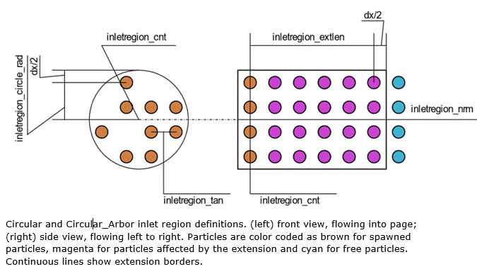
Figure 1.
Inlet Stencil
A stencil is created for the inlet region, which behaves as a source of particles. This is exported as a .txt file for the inlet region containing the coordinates (x, y, z) of the particles, which are to be inserted into the domain.
The spacing of the stencil must match the dx value used for the rest of the simulation.
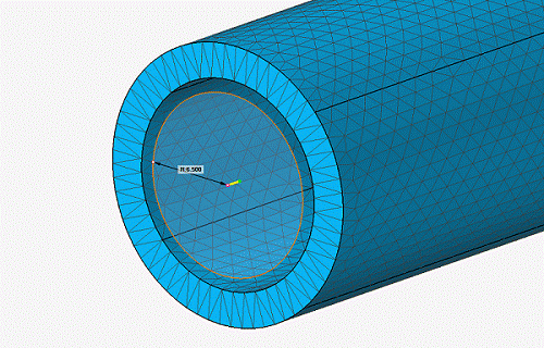
Figure 2.
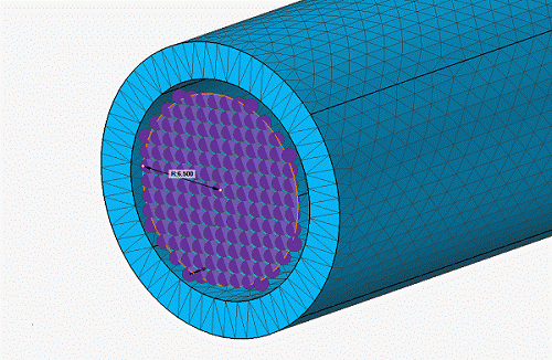
Figure 3.
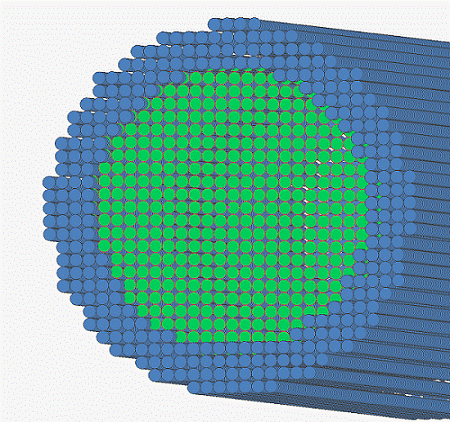
Figure 4.
As the fluid particles leave the extension, the distance between fluid-fluid particles and fluid-wall particles are not similar. This results in a pressure rise on the side where fluid particles are closer to the wall. Depending on the severity of the misalignment, this may result in undesired secondary flows.
Inlet Extension
The extension imposes the inlet velocity and ensures the distance between different spawn layers remaining at dx. As a result, extension is an important component of the Inlet region.
The extension covers up to half dx, further in each direction than the definitions given in the .cfg to ensure all spawned Inlet region particles are covered. The fluid particles within the extension have the same velocity as the Inlet region. It is important that the spawn area is not disturbed by other fluid particles. The extension only applies to the fluid phase specified for that specific Inlet region.
While possible, disabling the extension is generally not recommended unless it is guaranteed that the spawn area will remain undisturbed during the active interval of the Inlet region. Moving Inlet regions always requires an extension to function properly.
- Start Time / End Time
- Specifies the start and finish times which define the window where the Inlet region is active.
- Ramp Up / Down Time
- This parameter specifies a time window for the acceleration and deceleration of the fluid. At the start time, the flow will ramp up from zero to the specified value over this time. If ramp down is specified, the velocity will ramp back down to zero prior to the end time. This minimises pressure fluctuations and instabilities caused by instantaneous changes in velocity.
- Other Options
- A free text box where additional parameters can be specified.