Particle Generation
Particle Spacing
Particle spacing is the distance between adjacent particles in the global coordinate axis. The particles are uniformly distributed along the global XYZ axis. This spacing is used when generating the particles for stationary parts, moving parts, and the fluid regions.
Body Type: Fluids
This option helps to define and create the fluid (liquid and gas) regions inside the container. This is useful when the CAD or FE model does not have a separate body for the fluids.
Select the model for which fluid particles are to be created. In addition, a free node inside the fluid is to be selected. The mesher will automatically identify the wetted surface (surface that is touched by the fluids) and create a fluid volume. Particles for either Fluid 1 or Fluid 2, or both, can be generated as required.
- By plane
- Define Fluid Level defines a plane that separates the fluids (liquid and
gas) and its normal points to the Fluid 1 region.
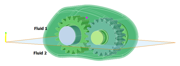
Figure 1.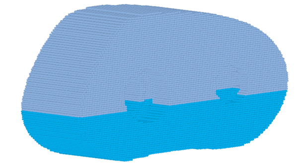
Figure 2. - By percentage of Fluid1 in total volume
- This option generates the fluids based on the specified percentage of
the total fluid volume. The reference plane is used to set the gravity
direction and which fluid is Fluid 1.
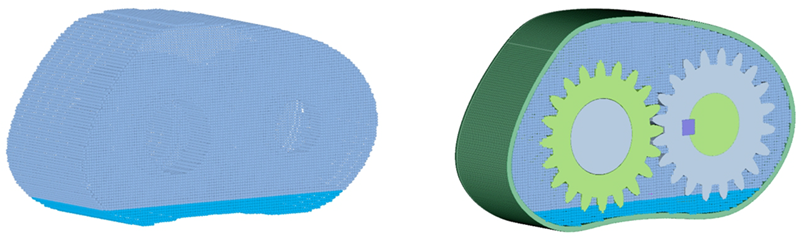
Figure 3. - By Fluid1 volume in litres
- This option generates the fluids based on the specified Fluid 1 volume in liters. The reference plane is used to set the gravity direction and identify which fluid is Fluid 1.
- The total fluid capacity of the below mentioned gear housing model is 1
liter. 0.15 liters of Fluid 1 particles is obtained as shown in Figure 4.
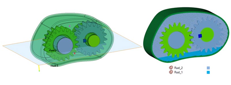
Figure 4.
Body Type: Solid
This option is used to create particles for the bodies selected as Moving solids, like gears, shafts, or casings. Particles will be created inside the solid region. To reduce model size, you can model the solids as a thick solid (hollow inside) without impacting the results. To facilitate this, you can specify a finite number of layers of particles needed from the solid surface. If the number of layers is specified as zero, all the particles inside the solids will be created. This can also be used for liquid or gas regions modelled as solids in the geometry.
Body Type: Container
Sometimes the outer casing can have features like bolt holes or ribs which do not impact the solution. It is more efficient to generate the model without these features. This is achieved by identifying solids that define the container (should not include the moving parts, should be closed, and should not have gaps bigger than the particle distance) and a point inside the container where the fluids are present. The mesher will automatically identify the wetted surface (surface that is touched by the fluids) and create several layers of particles away from the wetted surface.
In the below model, the Moving solids (gears/shaft) are modelled as solids. While creating particles for Container, the Moving solids should be ignored. Hence, the bodies that would be considered for creating a Container, are bodies from the Model minus Moving solids.
Automatic Leak Detection
When generating particle mesh for Liquid, Gas, and Container, any present leak paths will be displayed.
Automatic Materials and Motions Transfer
When generating particles, if Materials and Motions are defined for the input bodies, the output particle mesh will inherit the same materials and motions. For Fluid 1, Fluid 2, and Container, you can select the Material to be assigned automatically after generating the particle mesh for the components. When an active SPH Flow Solution exists, the output particle bodies are automatically added to the Solution Mesh bodies. If the Solution already contains a particle mesh, the newly created particles replace the existing particle body.
Conflicting Fluid Particles
When particle generation for all three types (Fluid, Solid, Container) is enabled, a new body called Conflicting Fluid Particles (CFP) may be generated. The CFP body contains particles from the fluid volume which are in close proximity to mutiple bodies, so their assignment is indeterminate. Typically, this is in regions with narrow gaps or where the particle pitch is too large to resolve the geometry sufficiently. Ambiguous particles are written to the CFP body so you can decide which volume/body they should be assigned to.
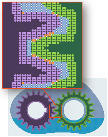
Figure 5.
A simple approach is to delete the CFP Body, which gives the same behavior as earlier generations of SimLab.
A more diligent approach is to use to combine the particles with the other particle bodies. In most cases the CFP Body can be safely merged with the fluid body(s). However, it is strongly recommended to review the CFP locations as in some cases merging with the solid bodies is more appropriate. The Create/Modify Particles menu may be useful to split the CFP Body when this is required.
Overlapping Particles
Particles which are closer than 0.9*dx are classed as overlapping. This can result in instability during a nanoFluidX simulation and may lead to unphysical forces.
- Identify Duplicates
- To check for duplicate nodes, select particle bodies and enter a tolerance (it is recommended to start with 0.1*dx). Show Body Pairs will search and populate the table with the body pairs containing duplicate nodes. If the body itself has duplicates nodes (self intersection), then the corresponding body name will be added in both Preserve Body and Delete Body.
- Remove Duplicates
- Use Swap Pair to decide which body particles are to be retained and which are to be deleted to resolve an overlap.