Altair Multiscale Designer 2022 Release Notes
Highlights
Important: All Multiscale Designer material models
(*_mdsMAT.dat) will need to be re-run through the
Multiscale Designer GUI material model development process (Linear Material
Characterization and Nonlinear Material Characterization) to update the material
model files to v2022 (and beyond).
- Injection Molding Fiber Orientation Tensor Mapping in HyperWorks/HyperMesh
- Auto-stop Criteria for Abaqus Interface
- Complete Integration with OptiStruct (MATMDS) and Radioss (/MAT/MDS)
- Generalized Tension/Compression for N-Phase Material Models
New Features
- Injection Molding - Fiber Orientation Tensor Mapping - HyperWorks Automated Workflow
- A new improved usability workflow for the fiber orientation tensor mapping process has been developed within HyperWorks. The entire guided workflow is now performed within HyperWorks and there is no longer any need to return to the Multiscale Designer GUI for this process. Version v2022.1 will have further integration of this workflow in a HyperWorks ribbon bar, which will remove running the scripts, and launch the workflow direction from the ribbon bar. However, in v2022, you can launch the workflow in HyperWorks by running the following scripts in order via :
- Auto-stop Criteria for Abaqus Interface
- A new capability to auto-stop an Abaqus multiscale job on user defined criteria has been developed. The capability requires that the file [solution_mdsconf.dat] exists in the run directory with the following information:
- Complete Integration with Radioss (/MAT/MDS)
- In v2021.0, the complete integration between OptiStruct and Multiscale Designer, with the addition of the OptiStruct material card (MATMDS), was introduced. This development enabled the usage of an already developed Multiscale Designer material model (*_mdsMAT.dat) within an OptiStruct simulation via a MATMDS definition directly within HyperWorks/HyperMesh, without having to return to the Multiscale Designer GUI. The same has now been enabled for Radioss in v2022.0 with the Radioss material card (/MAT/MDS). You can now develop complete multiscale simulations for OptiStruct and Radioss directly within HyperMesh/HyperWorks without having to leave the pre-processor. All Radioss element and property types can be used with Multiscale Designer material models. OptiStruct element and property type support is given in the “Enhancements” section below.
Enhancements
- OptiStruct - Multiscale Designer Interface
- The following matrix highlights the multiscale simulation support
OptiStruct has for Multiscale Designer material models. “Gray” areas are
currently being developed for future releases, and an all “Green” areas
are expected within a couple of release cycles.
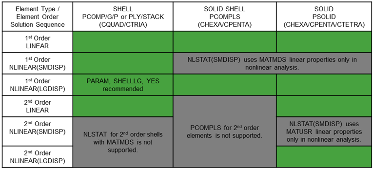
Figure 1. - Generalized Tension/Compression for N-Phase Material Models
- In prior releases, Multiscale Designer material models were limited to 2-phase tension/compression behavior. A 3rd phase could not exhibit tension/compression behavior. For example, this was limiting for woven materials, which have three phases (matrix, towX, and towY). In the current v2022.0 release, a generalized tension/compression formulation has been developed which allows for N-phase materials to have tension/compression behavior defined. Therefore, the prior release limitation to 2-phase materials has been removed with this release and any Multiscale Designer material model can now have N-phase tension/compression behavior defined and accounted for correctly in the material model.
- External Unit Cell Tolerance Enhancement
- In prior versions, many external unit cells failed due to tolerancing issues associated with finding periodic boundary conditions with non-prismatic external unit cells. To increase the robustness of these types of external unit cells, the addition of a user defined tolerance value can be selected to facilitate the successful definition of periodic boundary conditions. If an external unit cell fails, simply increase the tolerance selection (from the new drop-down selection in the External Unit Cell GUI) and re-run until successful.
- Injection Molding Laminate Definitions
- In v2022.0, for Injection Molding Laminate definitions, the ability to define the number of slices and averaging or individual results method is exposed to the user in the Laminate definition GUI. These definitions can be used to obtain more accurate injection molding simulations in certain cases.