Imprint Geometry
Use the Imprint tool to imprint geometry onto target surfaces or lines, thus creating new fixed points or edges.
Imprinting points on lines or surfaces creates geometry vertices similar to using the Split: Interactive tool. Imprinting surfaces onto surfaces imprints all of the source surfaces' edges onto the target surfaces.
The imprint direction is always normal to targets.
-
From the Geometry ribbon, click the Imprint tool.

Figure 1. - Optional:
On the guide bar, click
 to define imprint options.
Tip:
- Split multiple surfaces with multiple lines at once.
- Use the Split: Interactive tool to untrim previously imprinted surfaces.
- Use the Stitch tool to suppress imprinted edges.
CAD Options
- Maximum imprint distance
- Use maximum imprint distance between source and target geometry.
- Maximum distance
- Enter an imprint distance.
- Line extension method
- Select a line extension option.
- Keep line endpoints
- Keep line endpoints when extending lines.
- Surface imprint method
- Select which lines to imprint.
- Do not imprint internal edges
- Skip internal edges and common edges of selected surfaces.
- Do not imprint near existing edges
- Skip edges too close to pre-existing features.
FE Geometry Options
- Maximum imprint distance
- Use maximum imprint distance between source and target geometry.
- Maximum distance
- Enter an imprint distance.
- Post imprint options
-
- None
- Simple method to imprint source on target surface.
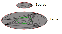
Figure 2. - Create patch between imprinted edges
-
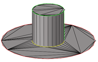
Figure 3. - Move target imprint edges to source
-
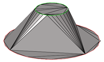
Figure 4. - Move source to target
-
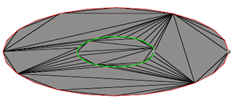
Figure 5.
- Minimum gap detection
- Select the minimal allowed gap size.
- Minimum gap size
- If the distance between the imprinted and pre-existing lines is smaller than this value, then the edge is skipped during imprinting.