In the Generate tab, define the following options, which will be used to generate the
comparison results.
The options available in this tab will vary depending on the Location you select.
Click the Generate tab.
From the Location list, specify where the entities you are comparing can be
found.
Choose Auto to generate results for entities positioned at
any location, by automatically calculating a transformation matrix between the source
and target entities. A maximum of one match for each source entity will be found. This
option is only available for CAD-CAD comparison.
Choose Position to generate results for entities positioned
at a location that you specify. For the Source entities and the Target entities
collectors, select up to three locations on the source that correspond to the same three
locations on the target. This option will use these locations to define the
transformation of the source entities to the target entities. A maximum of one match for
each source entity can be found.
Choose Recursive to generate results for entities
positioned at any location, by automatically calculating transformation matrices between
the source and target entities. Multiple matches can be found for each source entity. A
source entity may match more than one target entity positioned at a different location.
This option is only available for CAD-CAD comparison.
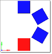
Choose Rotate to generate results for entities rotated
about a vector. Multiple matches may be found for each source entity, depending:
Axis
Select a collector that defines the rotation axis/vector.
Angle
Specify the rotation angle to search and find target entities.
Steps
Specify the number of times to increment the angle value when searching.
For example, in the image below, assume the red element is the source, the blue
elements are the target, and the z-axis is the rotation vector. If the angle = 60
and the steps = 1, then only the first blue element will be found. If the steps =
2, then the first two blue elements will be found. If the steps = 3, then all
three blue elements will be found. Similarly, if the angle = 30 and the steps = 1,
then no blue elements will be found, but if the steps = 2, then the first blue
element will be found. Figure 1.
Choose Same side to generate results for entities
positioned at the same location. A maximum of one match can be found for each entity
source.
Choose Symmetry to generate results for entities positioned
symmetrically about a plane. A maximum of one match can be found for each source entity.
When you select this option, the Symmetry plane selector becomes active. Use the
Symmetry plane selector to select the plane about which the symmetry exists.
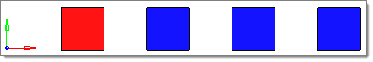
Choose Translate to generate results for the entities
translated along a vector. Multiple matches may be found for each source entity,
depending on:
Direction
Select a collector that defines the translation vector.
Distance
Specify the translation distance to search and find target entities.
Steps
Specify the number of times to increment the distance value when searching.
For example, in the below image, assume the red element is the source, the blue
elements are the target, and the x-axis is the direction vector. If the distance =
2 and the steps = 1, then only the first blue element will be found. If the steps
= 2, then the first two blue elements will be found. If the steps = 3, then all
three blue elements will be found. Similarly, if the distance = 1 and the steps =
1, then no blue elements will be found, but if the steps = 2, then the first blue
element will be found. Figure 2.
In the Tolerance field, enter the tolerance to use for comparing entities, in model
units.
A smaller value will lead to a more strict interpretation, while a larger value will
lead to a looser interpretation.
The tolerance is not used to remove features smaller than the tolerance value. All
features for a surface or mesh are considered valid for comparison regardless of their
size, and must be within the tolerance of a similar feature on the compared entities for
the surfaces or elements to be considered matched or overlapped.
For Result type, select the level of detail for the results.
Higher levels of detail require more calculation and processing time. Each level of
detail produces different results based on the type of comparison you are performing. For
detail description of the result types, refer to Comparison Result Types.
Optional: Perform a comparison a shells using their thickness.
Select the use thickened shells checkbox.
Restriction: Only available when you are comparing FE-CAD/CAD-FE.
To keep the internally calculated fillet distance relatively small, meaning that
elements near fillet regions must also be close to the surfaces to prevent them from
being marked as intersected, select the Match fillets
checkbox.
Fillets are assumed to lie nearby fillet roots, which are located at all
t-intersections and bends in the mesh of at least 44 degrees. Any nodes within an
internally calculated distance of a fillet root are treated as being inside the
fillet, and therefore they cannot cause an element to be marked as intersected. When
you clear the Match fillets checkbox, the internally calculated distance will be
relatively large, preventing many elements in fillet regions from being marked as
intersected if they are not close to the surfaces.
The internally calculated fillet distance is based on the thickness of the elements
touching the fillet root and the average thickness in the model. It is not a precise
determinant of the actual fillet region and is only intended to prevent elements
that are not close to the surfaces due to the presence of fillets from being marked
as intersected. As a result, most models with fillets will have elements in the
fillet regions marked as overlapped or intersected rather than matched.
Note: Clearing the Match fillets checkbox may cause the internally calculated
fillet distance to be rather large for certain models, and may potentially mark
elements as overlapped when they would otherwise be marked intersected due to the
element's edges not matching surface lines.
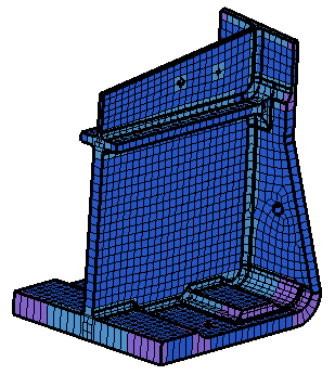
Use the Ignore holes/slots option to specify which holes and/or slots in the
surface data to ignored during the comparison.
If the features are smaller than the specified Holt/slot diameter and/or Slot
length criteria, then they will be ignored. Element edges in the region of an ignored
hole or slot are not required to be within the tolerance of a surface line. Element
nodes over an ignored hole or slot cannot cause the element to be marked as
intersected. Figure 3.
To use the normal projection of the centroid of an element to help determine with which
surface an element should be associated, select the Include element
centroids checkbox.
Without this option, elements are associated with a given surface based on the largest
number of their nodes which are within the given tolerance of that surface. If an
element has the same number of nodes within the given tolerance of more than one surface
the association will be made arbitrarily. This option uses the projection of the element
centroid to remove any ambiguity as to which surface is the best fit.
Additionally, elements that lie partially or completely off the edge of a surface will
be marked as unmatched instead of intersected if the projection of the centroid does not
lie on any surface. This option is particularly useful when comparing coarse meshes to
highly curved surfaces.
This option is turned off by default because it can substantially increase the time
spent comparing meshes if there are a large number of ambiguous elements.
Restriction: Only available for CAD-FE/FE-CAD comparisons.
To refacet all the surfaces in the model so that their facet size will be roughly equal
to that of the compared elements, select the Refined facets
checkbox.
This option is particularly useful when comparing highly curved geometries to FE meshes
with a tight tolerance.
The Comparison tool uses surface facets, rather than the surfaces themselves, to
quickly compare elements to surfaces or surfaces to surfaces. Often the default facets
can be long, thin triangles which only roughly capture the surface curvature in highly
curved areas. While the default facets can often be “close enough” to the surfaces they
represent, nodes of an element which lie exactly on the surface may actually lie outside
the given tolerance of the nearest surface facet. If this happens, the elements attached
to that node will be marked as intersected or unmatched instead of overlapped or
matched.
One solution to this problem is to increase the tolerance, but there are times when
using a large tolerance will be undesirable. For those times you can select this option
which will recalculate the facets for the surfaces such that they more closely adhere to
the actual surfaces. The result will be more accurate results with more elements marked
as matched or overlapped instead of intersected or unmatched.
This option is turned off by default because it can substantially increase the time
spent making the comparison.
Restriction: Only available for CAD-FE/FE-CAD
comparisons.