Transfer Path Details
To view transfer path details, select .
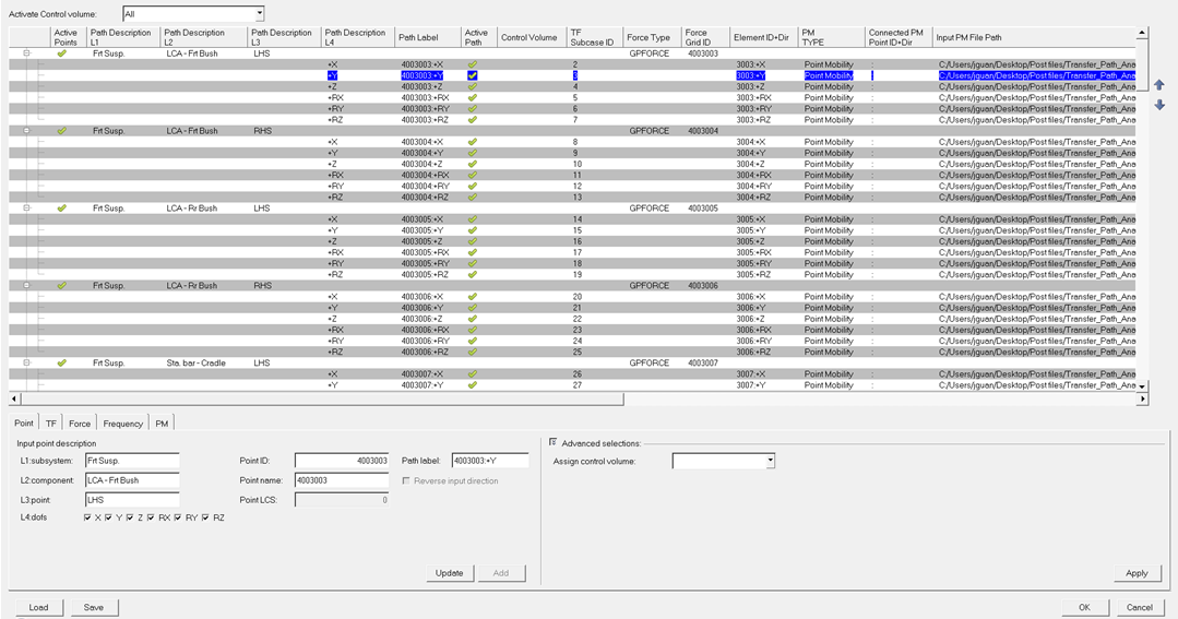
Figure 1.
The Path Details dialog is divided into three parts:
- The path control volume activation area, which allows you to activate paths in any control volume defined.
- The path detail configuration table, which allows you to view path details in a summary table format.
- The path detail management tabs, which allows you to define path details.
- Load
- Click Load to load a previously saved TPA configuration file.
- Save
- If any path detail information was entered through the dialog interface, click Save to save the information, which can be saved as a TPA configuration file.
- OK
- Click OK to keep any change made, close the Path Details dialog, and return to the sub-tab.
- Cancel
- Click Cancel to discard any change made since the path detail configuration was last saved, close the Path Details dialog, and return to the sub-tab.
Point
- Input point description
- Used to describe the physical point, typically an attachment or
connection point, associated to some transfer paths. It is divided into
four levels, and these levels are used to aggregate contributions from
all points sharing similar descriptions:
- L1: subsystem
- Enter a name for the subsystem the point belongs to, for example, Frt Susp.
- L2: component
- Enter a name for the component the point belongs to, for example Strut Cntr Mnt.
- L3: point
- Enter a name for the point, for example, LHS.
- L4: dofs
- Select DoFs at the point that paths are defined for.
- Point ID
- Enter the grid ID of the point.
- Point name
- Enter the name of the point.
- Point LCS
- Enter the analysis coordinate system, if any, defined at the point.
- Path label
- Label used to identify paths defined at the point.
- Reverse input direction
- Specify the reversed direction from the vehicle coordinate system.
- Advanced selection
- Specifies which control volume the point belongs to.
- Assign control volume
- Select a control volume and assign the point to it.
TF
- Path label
- Label used to identify the path for which details are specified on this tab.
- TF file path
- Select a TF file to load, if needed.
- Subcase ID
- Select a subcase to be used for this path.
- Subcase label
- Subcase label corresponding to the Subcase ID above.
- Advanced selection
- Options to view or modify the TF.
- TF type
- Select a TF type from the list of available types.
- Response ID
- Select a TF response ID from the list of available IDs.
- Component
- Select a TF component that a TPA can be performed for.
- Use modified TF
- There are two ways to modify the TF for a response
contribution study:
- Scale TF – Scales the TF value.
- Use target value – Uses a target value.
Force
- Path label
- Label used to identify the path for which the details are specified on this tab.
- Force file path
- Select a force file to load, if needed.
- Force type
- Select the type of available force to be used.
- Grid ID
- Select the ID of the grid at which the force has been recovered.
- Element ID
- Select the ID of the element whose force is to be used.
- Component
- Select the component of force to be used.
- LCS
- Specify the local coordinate system in which the force is output.
- Reverse force direction
- Reverses the force direction in the local coordinate system specified above.
- Advanced selection
- Options to view or modify the force.
- Subcase ID
- Select a subcase to view or modify force.
- Subcase label
- Subcase label corresponding to the Subcase ID above.
- Use modified force
- There are two ways to modify the force for the response
contribution study:
- Scale force – Scales the force value.
- Use target value – Uses a target value.
Frequency
- Path label
- Label used to identify the path for which the details are specified on this tab.
- Frequency table
- List of frequencies where results are available or to be calculated.
- Advanced Selections
- Specifies the frequency-based or RPM-based forces. By default, the option is set to frequency. If RPM is selected, then orders can also be assigned.
- Global TPA frequency selection
- Frequencies at which TPA is performed, and applies to all TPA paths.
- Global interpolation
- Select interpolation methods to be applied to TF, force, or TPA.
PM
- Path label
- Label used to identify the path for which details are specified on this tab.
- Mobility type
- Select the type of mobility to be displayed. Options include: point mobility (V/F), point inertance (A/F), or point receptance (D/F).
- Add connector mobility to
- Select the point to add a connector mobility to in a mobility mismatch plot.
- Input/Connected PM file path
- Select a PM file to load, if needed.
- Subcase ID
- Select a subcase to view.
- Label
- Subcase label corresponding to the Subcase ID above.
- Point ID
- Select the ID of the grid where the PM is calculated.
- Component
- Select the component of the PM to be displayed.