Transfer Path Analysis
Identifies the complex contribution of the excited structure through attachment points to a response in the responding structure.
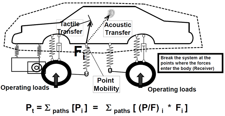
Figure 1. TPA process
Control Volume
A control volume is a visually convenient way to define transfer paths. Simply draw a window, such as the one above using dashed lines, that encloses the responding structure. All boundary elements cut through by the window, or the control volume, are connection elements used to calculate TPA forces, and their attachment points to the responding structure are the transfer paths used to calculate TPA transfer functions that need to be included in the TPA analysis. There can be multiple ways control volumes can be defined involving differing transfer paths. For example, when performing TPA on a front wheel drive vehicle, the front subframe can be included in the control volume if the user’s interest is in suspension to the subframe attachment point, or it can be left out of the control volume if engine mounts are of interest. Multiple control volumes can be defined in the TPA tool, but only one is activated in each TPA analysis.
TPA with Assumed Forces
If realistic forces are not available, a TPA analysis can be carried out using only the transfer function result file, with the force file field left blank. In this case, you will be prompted to enter force values, assumed to be constant over all analysis frequencies. The TPA utility will then automatically generate a force punch file to allow the TPA analysis to proceed. Typical practical scenarios where a TPA with assumed forces can be useful include ranking transfer functions to identify critical paths and frequencies based on either unit assumed forces, or target assumed forces.
Required Results Files
- The Transfer Function output file contains cross transfer function results between the attachment DoFs and the response points for which a TPA analysis is desired (from Step 1d). Optionally and preferably, driving Point Mobility (PM) results are also available in this file and allow you to examine local attachment stiffness effects.
- The Force output file contains attachment forces from Step 2b. It is assumed
that the forces are output using a local coordinate system (LCS) aligned
with the one used for the TF output. The easiest way to ensure consistency
is to use the GPFORCE output request using OptiStruct. The commonly use
force requests are:
Force Request Type Output LCS Comment GPFORCE Grid analysis LCS Same as force input LCS ELFORCE Element LCS May differ from the input LCS SPCFORCE Grid analysis LCS Same as force input LCS
Defining Transfer Path Details in the TPA Utility
Each transfer path is represented by a subcase in the TF file. Therefore, the TPA Utility reads subcases from the TF file to build a list of transfer paths available for analysis. In addition, a subcase labeling convention has been established to allow automated assignment of path details by the TPA Utility.
- TF Subcase Labeling Convention
Excited Grid ID:DoF<>Connector Element ID:DoF<>L1:L2:L3:DoF- Example
4003003:+X<>3003:+X<>Frt Susp.:LCA - Frt
                                Bush:LHS:+X
Scenarios of TF subcase labels
- No label, or unexpected label.
- The Utility makes all TF subcases available in the Path Details dialog so that you can add transfer paths manually in the Point tab and assign the proper subcase to each path in the TF tab.
- Label includes only Part 1 - Excited Grid ID: DoF
- The Utility builds a list of transfer paths in the Point tab, and assign the labeled subcase to the corresponding path in the TF tab. You will need to manually assign forces to the paths in order to proceed with the analysis.
- Label includes Part 1 and Part 2 - Connector Element ID: DoF
- The Utility builds a list of transfer paths in the Point tab, and assign the labeled subcase to the corresponding path in the TF tab, and assign force data matching the Grid and/or Element ID to the proper path in the Force tab.
- Label includes all three parts.
- The Utility builds a list of transfer paths and adds proper descriptions to the attachment point in the Point tab, assigns the labeled subcase to the corresponding path in the TF tab, and assigns force data matching the Grid and/or Element ID to the proper path in the Force tab.
The Automated TPA Process (one-step TPA)
The traditional TPA involves two solver runs, and can be fairly complex to setup to ensure that results from the two runs are consistent with subcases properly labeled as input to the TPA utility. A simplified process has been developed in OptiStruct that allows the necessary data needed for the TPA analysis to be requested (using the PFPATH card) in a single frequency response analysis run, where transfer path participation, along with associated transfer function and force data are output into a .h3d file. With this approach, a separate transfer function run is not needed.
Once the resulting .h3d file is loaded into the TPA utility, transfer function results are automatically matched up to force results that are guaranteed to be consistent. The automated TPA process significantly improves the efficiency and robustness of the TPA analyses.
The transfer path labeling can be significantly enhanced, if a tagpoint mapping file, which is automatically generated by the Analysis Manager functionality of the NVH Director, exists in the same folder where the .h3d file is located. The TPA tool will use the information from the mapping file to automatically create detailed path descriptions.