Stress Life Method (Conventional SN)
Stress Life approach for the seam weld fatigue is an extension of the regulation-based fatigue evaluation using the HyperLife Weld Certification workflow.
Implementation for Seam Weld Fatigue
With the Stress Life approach seam weld fatigue analysis is based on directly calculating the stresses within a certain evaluation distance from the weld line. The evaluation distance is calculated by either nominal or hotspot approaches. The damage evaluation is only conducted at the root locations, as shown in the image below (T weld example).
Read more about Uniaxial Fatigue Analysis, using S-N (stress-life) approach for predicting the life here Uniaxial Fatigue Analysis.
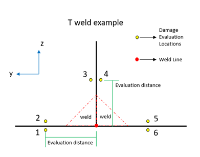
Figure 1.
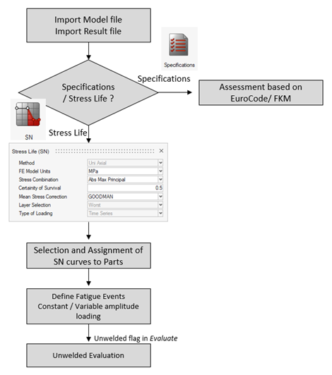
Figure 2.
The SN curve selection is made from the Material context, from either of the available options, i.e. Material DB, My Material and HM Material, all these options will allow selection of Amplitude based SN curves. The selected materials will be populated for weld locations selection in Points context and in Assign Material data for Parts.
Refer to Define Weld Evaluation Point Properties for steps in weld material assignment for SN evaluation.
SN evaluation in HyperLife Weld Certification supports Time Series loading and allows creation of Superposition or Sequential fatigue events. Refer: Create Events.
List of Evaluation Distance Parameters
| Evaluation Distance | Reference distance to find the evaluation location from the weld element at which the stress values are extracted. Read more: Find Evaluation Positions. |
| Weld Width | Width of the weld material from the web wall. This parameter is ignored if specifying the evaluation is done manually. |
List of General Classification Parameters
| Scale | Scale is used to modify the calculated stress during the stress history generation. |
| Offset | Offset is used to modify the calculated stress during the stress history generation. |
| Kf | Fatigue strength reduction factor. Default = 1.0 Read more: Other Factors Affecting Fatigue (Fatigue Strength Reduction Factor) |
List of Parameters
| Weld Detail Category - Transverse Location_X | SN curve considered for the calculation of fatigue and cutoff limits of the normal stress component in the transverse direction (perpendicular to the axis of the weld) at X. |
| Weld Detail Category - Longitudinal Location_X | SN curve considered for the calculation of fatigue and cutoff limits of the normal stress component in the longitudinal direction (parallel to the axis of the weld) at X. |
| Weld Detail Category - Shear Location_X | SN curve considered for the calculation of fatigue and cutoff limits of the normal stress component of the shear stress component at X. |