Detect Weld Lines
Detect the welds in components which are currently visible and organize them in the weld line browser.
- node to node
- Plate components are connected using common nodes or shared edges.
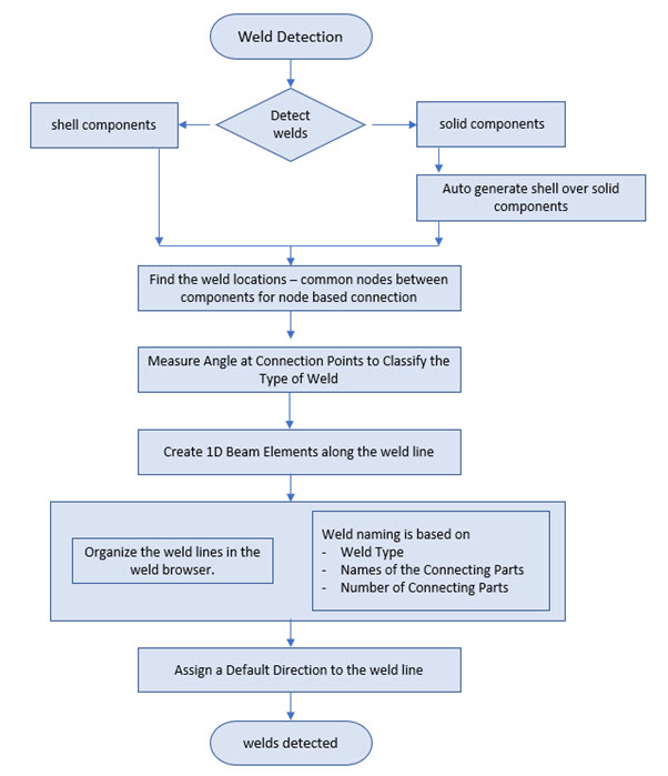
Figure 1.
-
Click the Mark Welds tool.

Figure 2.The Mark Weld dialog opens. -
Click Detect.
HyperLife Weld Certification automatically detects all the weld lines that are present in the visible components and highlights them in red.Note:
- Other components which do not need weld detection can be hidden prior to detecting welds.
- If there are already welds in the model, either added manually or otherwise, HyperLife Weld Certification displays a message asking if you'd like to retain or delete the existing weld lines.
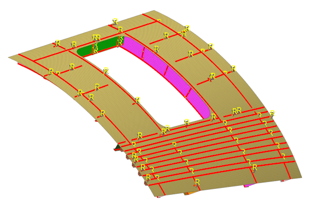
Figure 3.Both the weld line browser and the Weld Lines folder in the HyperLife Model Browser are populated and categorized according to weld type.
-
Review welds populated in the weld line browser of the
Mark Weld dialog.
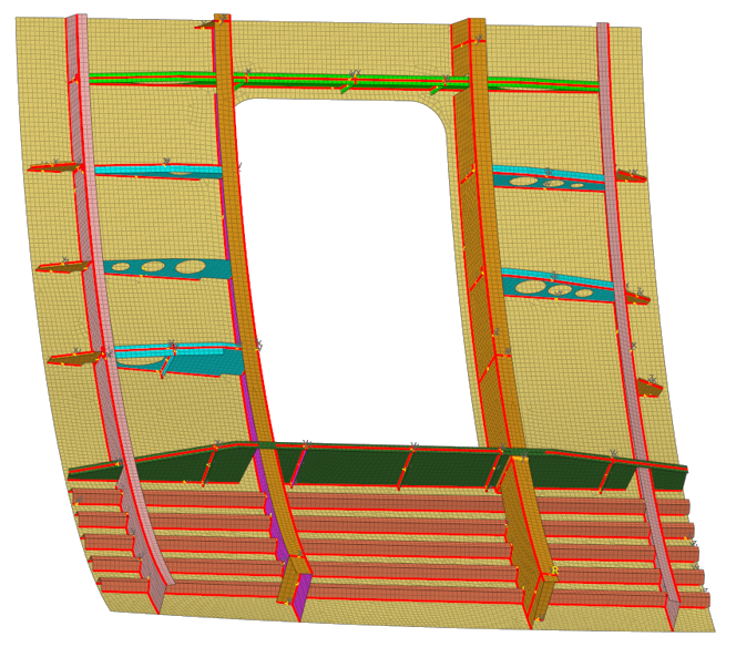
Figure 4. Detected Weld Lines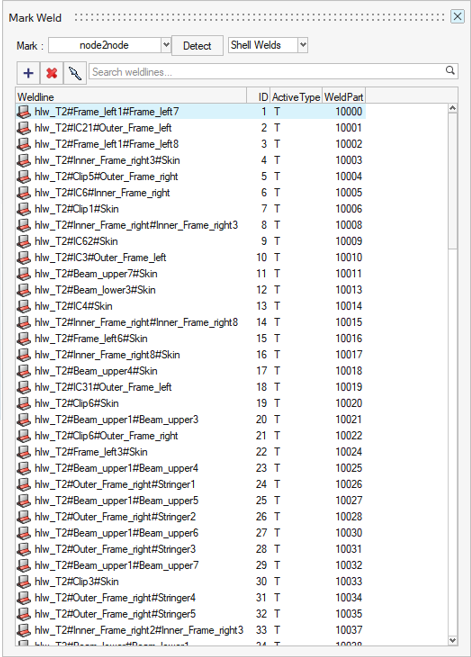
Figure 5. Corresponding Active Weld Types - Optional:
In the Mark Weld dialog, change the active weld
type.
Weld types T and Cross can be edited in the weld line browser to change the type of weld auto detected.
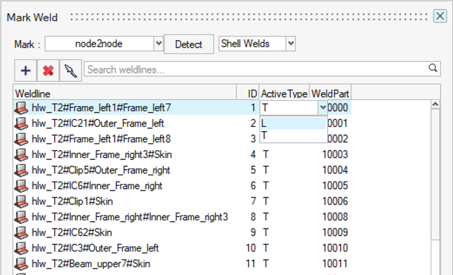
Figure 6. Change Weld TypeFor example, a T weld can be changed to an L weld, to represent the weld line as a single sided weld fillet weld. This would change the number of toe elements evaluated for the selected weld.
The number of evaluation points change when the weld type changes. This can be reviewed in the Points context after applying a regulation. If T is changed to L, the number of locations listed in the location table of the Points context will change from six to four, see Figure 7.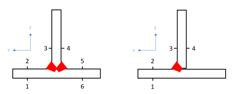
Figure 7. T Weld Changed to L Weld