PCD [Point Cloud Data]
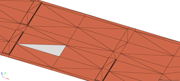
Figure 1. 3D Shell
Road File
- UNITS block
- MODEL block containing:
- Method as 3D
and
- ROAD_Type as PCD
- Method as 3D
- An optional PARAMETERS block containing the following:
- SEARCH_TRIAS: Option to set the search strategy to triangles. Default is true, if triangles are available. If false, the nearest three nodes are collected to interpolate. Additional details are available in the next section.
- OFFSET_ X: x coordinate of origin. Default is 0.
- OFFSET_ Y: y coordinate of origin. Default is 0.
- OFFSET_ Z: z coordinate of origin. Default is 0.
- HT_INTERPOLATION: The interpolation method used to get the height at contact patch. Available methods: Barycentric (default) or Linear.
- BEYOND_BB_Z: Height to be used outside the bounding box of the road.
- ROTATION_ANGLE_XY_PLANE: can be used to rotate the road on top of the road reference marker. Default is 0.
| Search Strategy | Interpolation Strategy | |
|---|---|---|
| Linear | Barycentric | |
| Nodes | Mean height of the nearest three entities | Weighted average of the nearest three nodes, based on distance. |
| Elements | Barycentric weight of nodes forming the enclosing element. | |
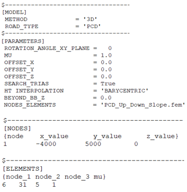
Figure 2. Sample .rdf File
If the tire is inside the biggest bounding box of the road but is outside the road patch, the previously seen height will be used.
Search Strategy
- Nodes and Elements
- Nodes only
- 1. Nodes and Elements
- The road surface data is given in the form of NODES and ELEMENTS. This data can be
provided in two ways:
- TABLE in the same .rdf file.
- File with Nodes and Element data.
- TABLE
- The NODES table consists of four columns. Column 1 being the node number/node
count, nodes are vertices. Column 2, Column 3 and Column 4 being the x, y, z
coordinate of the vertices of the triangle element.
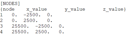 Figure 3. Nodes TableThe ELEMENTS table consists of four columns. Column 1, Column 2 and Column 3 being the node ID of the vertices making up the triangle element. Column 4 contains the coefficient of friction of the particular element. This information is not passed to tires currently.
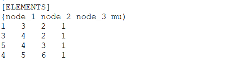 Figure 4. Elements Table
 - File with Nodes and Elements
- The file should be exported from HyperMesh using
the OptiStruct
.fem file with the options as shown below:
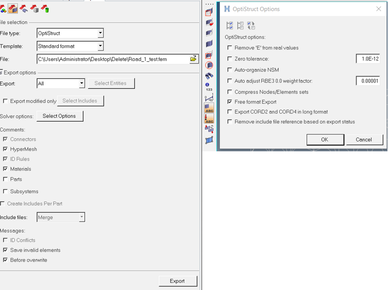 Figure 5. HyperMesh Selections for Exporting Node and
Element DataThis will export a .fem file with the data as shown below:
Figure 5. HyperMesh Selections for Exporting Node and
Element DataThis will export a .fem file with the data as shown below: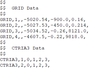 Figure 6. Node and Element Data from HyperMesh in
OptiStruct Format
Figure 6. Node and Element Data from HyperMesh in
OptiStruct Format
- 2. Nodes Only
- It is also possible to interpolate road height without element or connectivity data.
If a file does not have the connectivity data, the search strategy is automatically
chosen to use only Nodes. If you wish to not use the connectivity even if available,
this can be done using the keyword SEARCH_TRIAS=FALSE in [PARAMETERS] block.
With this strategy, the height interpolation works by obtaining the nearest three points to the tire contact point. These three points functions as the vertices of a virtual triangular element. Rest of the process is the same as the one with Element based height interpolation.
- Application
-
Both the search strategies have distinct advantages. You must decide one over the other. The following information may be useful to make the decision.
The advantages of an element-based height interpolation:- You can completely control the final intended road surface by controlling the
features captured in the mesh.
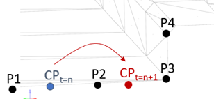 Figure 7. Height Interpolation Schema
The Figure above is a cross section of a road surface. CP is the tire contact point lying on a flat surface. P1, P2, P3, P4 are four points. The height of the road will be interpolated considering the closest three points of the CP. If CP is between the point P1 and P2, the height will be interpolated considering points P1, P2 and P3. If instead CP is between point P2 and P3, the height is computed using P2, P3, and P4. By controlling the mesh, users can also control the accuracy of height interpolation and as consequence the detailed representation of the road.
- The number of mesh elements can be controlled by creating a mesh. This will help in reducing the number of elements to be searched. The elements are cached for future reference as well. This helps in improving the CPU time. In case of points as there are no elements there is no data available for quick reference.
- Repeatability is present even if the CP shifts slightly between different simulations due to numerical approximations. As long the shift is within the element there will be no difference in the output value. But this cannot be guaranteed with only points because if a different point becomes closer then the interpolated height will be different.
However, you might want to interpolate a road height using only the nodes when:- Approximate results are enough to get an idea about the vehicle simulation.
- Meshing and obtaining a triangular mesh is not possible.
- You can completely control the final intended road surface by controlling the
features captured in the mesh.
Best Practices
- If the vehicle is kept on an uneven or a slant surface at the beginning, MotionSolve will have difficulties in obtaining a static equilibrium for the tire. It is advised to place the vehicle on a flat surface if such a problem occurs.
- Have as big elements as possible on flat surfaces.
- Use smaller elements only to capture the curvature of geometry.
Figure 8. Big elements for flat surfaces and smaller elements for capturing curvature - Try to avoid exactly vertical elements where there are nodes lying on the same x,y
point. Instead try to provide a small difference in the bottom and top nodes.
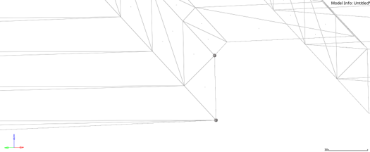
Figure 9. Avoid exactly vertical nodes as shown