SF Card
This card scales the geometric data.
On the Construct tab, in the Modify group,
click the ![]() Scale (SF) icon.
Scale (SF) icon.
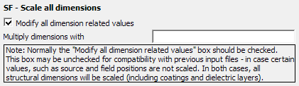
Figure 1. The SF - Scale all dimensions dialog.
This card is useful for specifying models in a convenient unit (for example cm) and
specifying a scaling factor once.
Note: By default Feko reads
all dimension related values as if specified in metres.
Parameters:
- Modify all dimension related values
- If this item is checked all geometrical dimensions are scaled. If unchecked, not all coordinate values are scaled (for example, the positions of near field calculations, see the list below). This should only be unchecked for backwards compatibility with old input files.
- Multiply dimensions with
- The scale factor. For example, if this is set to 0.001, all dimensions are entered in mm.
- Coordinates of the corner points of the triangular surface elements.
- Coordinates of the corner points of the segments.
- Radii of the segments.
- Coordinates of the corner points of the cuboids.
- Named points defined by the DP card.
- Radii of the all the layers when the Green’s function for a homogeneous or layered dielectric sphere is used.
- Thickness of the layers when the Green’s function for a planar, multilayered substrate is used.
- Coordinates of the corner points of the polygonal plates.
- Coordinates, radii and dimensions of UTD cylinders.
- Coordinates of the corner points of tetrahedral volume elements.
- Thickness of dielectric surface elements.
- Radius and thickness of a wire coating.
- Coordinates of wedges and edges in the PO region.
- Coordinates of the Fock region.
- Transmission line length and end point coordinates.
- The dimensions of the aperture used in the AP card, as well as the specified gridlines, and the amplitudes of the A5 and A6 dipoles which depend on the incremental areas.
- The three coordinates defining a near field aperture receiving antenna, as well as the specified gridlines.
- The three coordinates defining the position of a PCB source (AJ card).
- The three coordinates defining the position of an impressed current source defined using model solution coefficients (AM card).
- The three coordinates defining the origin in the local coordinate system (MD card).
- The variable Maximum identical distance, specified with the EG card, which controls whether two points are considered to be coincidental in space or separate.
- FDTD geometrical parameters, for example, coordinates of the voxel corner points.
- General non-radiating network end point coordinates.
- Cables – all geometrical parameters, for example, paths coordinates, shield / cross-section dimensions and thickness and probe position along the path length.
- Windscreens, for example, the top offset of a windscreen.
- The coordinates of the source point specified in the excitation cards A1, A2, A3, A5, A6, A7 (if the selection is not made by label).
- Coordinates of the origin of the radiation pattern specified with the AR card.
- Coordinates of the start and end points of the impressed currents for the AI and AV source cards, as well as the wire radius specified with these cards.
- Radii of the coaxial feed in the A3 card.
- Positions where the near field is calculated with the FE card.
- Offset in the near field calculation.
- Coordinates of the plane position for a transmission / reflection coefficients request.
- Coordinates of the L2 and L4 loads.
- Coordinates of the start and end points of the impressed electric current filament (AF and LF cards).
- Coordinates of the origin of the spherical modes source specified with the AS card.
- Coordinates defining the waveguide aperture (AW card).
- The “middle” coordinate for AI and AV sources.
- SAR (when the position is specified).
- Offset in the far field calculation (only near field– OF card).
- Receiving antenna coordinates of the origin for:
- Far field pattern
- Spherical mode pattern
Note: If all data is specified in the unit of mm, with the scaling set to 0.001, all
input values are interpreted as mm.
This also applies to the segmentation parameters
(IP card) and possible translations (TG card).