CO Card
This card specifies a dielectric or magnetic coating of wire segments or triangular surface elements.
In the Home tab, in the Define group, click
the ![]() Media icon. From
the ドロップダウンリスト select the
Media icon. From
the ドロップダウンリスト select the ![]() Coating (CO) icon.
Coating (CO) icon.
The CO card uses the material properties (label of the material) defined in the DI card. Therefore the DI card must be placed before the CO card. A layered medium is defined by referencing the labels of the materials to be used for the individual layers in the DL card.
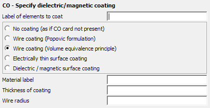
Figure 1. The CO - Specify dielectric/magnetic coating dialog, set to Wire coating (Volume equivalence principle).
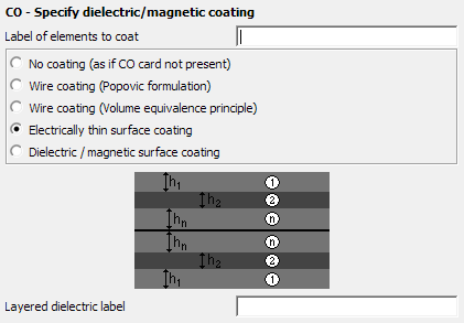
Figure 2. The CO - Specify dielectric/magnetic coating dialog, set to Electrically thin surface coating.
Parameters:
- Label of elements to coat
- All segments or triangles with this label are coated.
- No coating (as if CO card not present)
- No coating present (as if the relevant label has no CO card). This is used to remove wire coatings from earlier solutions.
- Wire coating (Popovic formulation)
- In this case, the radius of the metallic core is changed internally to model the change in the capacitive loading of the wire and a corresponding inductive loading is added. The only restriction of this method is that the loss tangents of the wire coating and of the surrounding medium must be identical (for instance both media could be lossless).
- Wire coating (volume equivalence principle)
- This setting retains the radius of the metallic wire. The effect of the dielectric layer is accounted for by a volume polarisation current. The only restriction of this method is that the layer should not be magnetic in nature. This means that the relative permeability as well as the magnetic loss tangent of the coating must be the same as those of the surrounding medium).
- Electrically thin surface coating
- This option adds multilayer dielectric/magnetic coatings to the surface triangles with the specified label. Different values for the permittivity and permeability of the layers are allowed, but the total coating must be electrically (that is relative to the wavelength in the coating) thin as well as geometrically thin (see the next item).
- Dielectric / magnetic surface coating
-
This option adds electrically thick multilayer dielectric/magnetic coatings to the surface triangles with the specified label. This option requires that the total coating should be geometrically thin (relative to the triangle size, and as a result of the triangle size, also to the free space wavelength) as well as the curvature radius of the surface.
This option may also be used when using the MoM / MLFMM and a single-layered, electrically thick, but geometrically thin coating is applied.- Only for closed structures with a PEC surface and the normal vector pointing towards the source(s).
- Coating is applied to both sides of the PEC surface, since fields will be zero where there is no sources.
- The accuracy of this option is higher when the propagation constant is high (high losses / permeability / permittivity).
- Material label
- Label of the material (as specified in the DI card) that will be used as a coating.
- Layered dielectric label
- Label of the layered dielectric medium (as specified in the DL card) that will be used as a coating.
- Thickness of coating
- For surface coatings, the thickness hn of each respective layer. For wire coatings this is the radius of the coating less the radius of the wire-core. This value is in metres and is scaled by the SF card.
- Wire radius
- Wire radius of the metallic wire, without layers, in metres (it is scaled by the SF card). This overrides the values specified in the IP card. This field is only applicable to wire coatings.
- The loss tangent
of the layer (which is calculated from the conductivity
and the relation
) has to be identical to the loss tangent of the surrounding
medium. Note: The surrounding medium usually is free space, and it is specified with the EG card.
- Due to the change in the radius of the metallic core, no SK card should be active for the same label, otherwise the skin effect and/or the ohmic losses refers to the wire with changed radius.
- For pure dielectric layers (that is the relative permeability as well as the magnetic loss tangent of the layer are equal to those of the surrounding medium) the option Wire coating (Volume equivalence principle) is recommended.
If the option Dielectric / magnetic surface coating (the electrically thick coating) is used, it must remain consistent for the whole Feko run. (It cannot be enabled for one solution and disabled for the next.) It is, however, allowed to change the thickness and the medium parameters of the coating.