AP Card
This card defines a planar, cylindrical or spherical aperture of measured or calculated field values that is converted by PREFEKO internally into an equivalent array of electric and magnetic dipoles (A5/A6 cards).
On the Source/Load tab, in the Equivalent
sources group, click the ![]() Aperture source (AP) icon.
Aperture source (AP) icon.
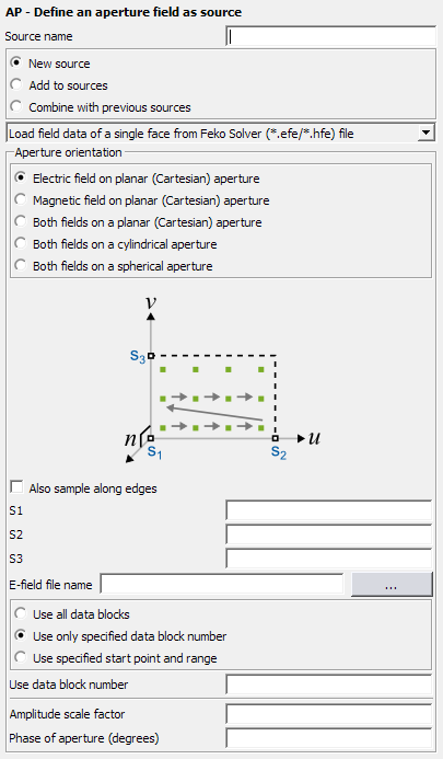
Figure 1. The AP - Define an aperture field source dialog.
Parameters:
- New source
- A new excitation is defined which replaces all previously defined excitations.
- Add to sources
- A new excitation is defined which is added to the previously defined excitations.
- Combine with previous sources
- Combine multiple aperture field definitions to create a single near field source.
- Load field data from
-
- Feko Solver (*.efe/*.hfe) file
- Read the field values from .efe/.hfe format files calculated by Feko. The files should contain values describing a single face. The field data files are requested with the DA card.
- Cartesian boundary from Feko Solver (*.efe/*.hfe) file
- Read the field values from ..efe/.hfe format files calculated by Feko. The files should contain values describing a Cartesian boundary. The field data files are requested with the DA card.
- CST near field scan (CST NFS)
- Read the field values from CST NFS format files.
- Sigrity (*.nfd) input file
- Read the field values from a .nfd file.
- Orbit/Satimo (*.mfxml) measurement file
- Read the field values from a .mfxml file.
- ASCII text file
- Read the field values from an ASCII file.
- The field data follows in the (*.pre) input file
- The field values are specified in the .pre file. The format of this file is described with the AR card.
- ...aperture
- Here one may select a planar, cylindrical or spherical aperture. For a planar aperture one may elect to use only electric or magnetic fields (this radiates in both directions, see comments below).
- Also sample along edges
- This item is used to determine if dipoles are allowed to be positioned on the edges of the aperture or not (see figures below). When checked the outer dipoles will be positioned exactly on the edges. When unchecked the dipoles will be positioned half an increment away from the edges. Dipoles should not be positioned on the edges of two apertures that have a common side, otherwise two dipoles may have the same location and polarisation. If this is the case the power calculation in Feko will fail.
- Swap source and field validity regions
- This item is used for Cartesian boundary, spherical and cylindrical apertures to interchange the side of the aperture where the fields are considered equivalent to the measured or calculated field values.
- S1, S2 and S3
- These text boxes are for input points (see the DP card) that define the orientation of the aperture. The figure on the dialog will depict the orientation. For a planar aperture the input points define the position of the origin and the direction of the and directions respectively. (The field data is assumed to vary first along the direction.) For cylindrical and spherical apertures they define the origin and the direction of the local Z 軸 and X 軸 respectively. All angles are relative to these axes.
- E-field file name
- The input file name from which the electric field data must be read. This may be either an .efe file or a text file (with units V/m).
- H-field file name
- The input file name from which the magnetic field data must be read. This may be either an .hfe file or a text file (with units A/m).
- Start from point number
- The number of the first field point to be used for the aperture. If set to 1, field values are read from the start of the file, for larger values the first point number-1 values (.efe and .hfe files) or lines (text files) are ignored. This may be used, for example, if the data file contains the field values for more than one frequency. This corresponds to the line number if all non-data lines are stripped from the file. The Start from point number field is not used if the field data is obtained from the .pre input file
- Number of points along...
- These two text boxes specify the number of field points along each of the two axes of the aperture.
- Aperture orientation
- Define the aperture orientation by specifying the reference points (S1, S2 and S3) in relation to the aperture.
- S1, S2 and S3
- Define the orientation of the aperture.
- File name
- The input file name from which the Sigrity (.nfd) or Orbit/Satimo (.mfxml) files are read.
- Use all data blocks
- Import all data blocks from the specified .efe/.hfe, .nfs, .nfd or .mfxml file. The data is interpolated for use at the operating frequency.
- Use only specified data block number
- Use the data from the nth frequency block in the specified .efe/.hfe, .nfs, .nfd or .mfxml file.
- Use specified start point and range
- Select a specific near field pattern in a .efe/.hfe (a single face), .pre or ASCII text file.
- Amplitude scale factor
- A constant by which the amplitudes of all the dipoles in the aperture are scaled.
- Phase of aperture
- A constant phase added to all dipoles in the aperture.
Therefore for planar apertures the positions are calculated entirely from the specified points (S1, S2 and S3). For cylindrical apertures the specified points (S1 and S2) define the extents of the aperture along the local direction and S1–S3 specifies the direction of the X 軸 as well as the radius of the cylinder. The points are placed at the -values listed together with the field data. For spherical apertures, S1–S2 specifies the direction of the Z 軸 and S1–S3 the X 軸. S2 and S3 must be positioned on the same radius which is also the radius of the field points. In this case both and are read with the data.

Figure 2. Location of the equivalent dipoles on a planar aperture where the Also sample along edges check box is selected.

Figure 3. Location of the equivalent dipoles on a planar aperture where the Also sample along edges check box is cleared.

Figure 4. Location of the equivalent dipoles on a cylindrical aperture: (a) Also sample along edges check box is selected (b) Also sample along edges check box is cleared.
In Figure 5, the dipole locations for a spherical aperture created from field values for from 40° to 80° with 10° increments and from 20° to 80° also with 10° increments. In this case the aperture increases in size in both directions when selecting the Also sample along edges check box.

Figure 5. Location of the equivalent dipoles on a spherical aperture: (a) Also sample along edges is checked (b) Also sample along edges is unchecked.
For planar apertures, the data must vary first along the direction. For cylindrical and spherical apertures PREFEKO will determine which coordinate is incremented first and write out the dipoles accordingly.
The dipole amplitude is the product of the surface current and the incremental area between samples. In addition, the amplitude of the dipoles on the sides (when checking Also sample along edges) are reduced by a factor of 2 and those on the corners by a factor of 4 to ensure that the effective aperture of integration has the same size as the specified aperture.
A fully closed surface can be created by specifying 6 planar apertures or a spherical one. The surface equivalence principle can be applied to this surface by reading both electric and magnetic fields for each plane. (For planar apertures the user should specify 6 AP cards, each using both electric and magnetic fields. If separate cards are used for the electric and magnetic fields the radiated power is not calculated correctly.) The normal vector must point towards the exterior region, which is normally outward. (For planar apertures created from .efe and .hfe files, the sample order determines the directions of and which, in turn, determines the normal vector . If this is pointing into the cube, an additional 180° phase shift is obtained by setting Phase of aperture (degrees) to 180. This changes the sign of the field radiated by the aperture which, when interacting with the remaining sources, will result in the correct total fields in the desired region. All surfaces and scatterers inside the body must be removed but not those on the outside.