RL-GO
With this option the RL-GO parameters are specified.
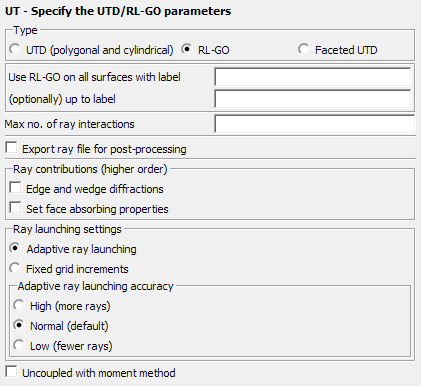
Figure 1. The UT - Specify the UTD/RL-GO parameters dialog, set to RL-GO.
Parameters:
- Use RL-GO on all surfaces with label
- The label to which the RL-GO should be applied
- (optionally) up to label
- The label up to which the RL-GO should be applied. RL-GO will not be applied to labels outside of the range between this field and the label in the previous field.
- Max no. of ray interactions
- This parameter gives the maximum number of ray-interactions (that is reflection and transmission combined). If for example, the parameter is set to 3, a ray can have 3 reflections, or 2 reflections and a transmission. If left empty, then the maximum number of ray interactions is determined automatically.
- Export ray file for post-processing
- When this item is checked the ray information is exported to the .bof and .ray files. Activate this option if ray paths are to be displayed in POSTFEKO where the ray information is read from the .bof file. The exported ray information may result in a large .ray file and a dramatic increase in the .bof file size. For parallel runs the run-time can also increase significantly when exporting ray data.
- Ray contributions (higher order)
- Determines which ray contributions to take into account.
- Ray launching settings
- Specify the settings for the launching of rays.
- Uncoupled with moment method
- This item specifies whether the coupling from the UTD region to the MoM region should be considered. This option should only be used when the UTD and MoM regions do not couple (interact) strongly.
The main advantages of RL-GO are as follows:
- It is suitable for large arbitrarily shaped objects (also curved objects).
- Dielectrics are supported.
- A plane wave source required for the calculation of far field RCS is supported (the UTD has a problem with caustics).
- Multiple reflections can be solved more efficiently than UTD or PO.
When no UT card is used, the following default values apply:
- Max no. of ray interactions: 3
- Write debug information to *.dbg: unchecked
- Export ray data for post-processing: unchecked
- Select ray contributions includes:
- Direct and reflected
- Edge and wedge diffracted rays
- Corner diffraction