HyperMesh (and OptiStruct) mesh export workflow
Introduction
This section presents the steps to follow in HyperMesh (V14.0) to export the mesh in a Nastran file.
Preliminary
Before detailing the workflow to follow, here are some useful information for a first HyperMesh using:
- To displace the geometry in the graphic area, the Ctrl key must be always pressed. To move by translation, use the right click. To move by rotation, make one left click to define the rotation center, then move the mouse with the left click.
- To select objects (faces, solids, etc.), make a left click on each object. To unselect objects, make a right click on each object.
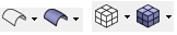
- The transparency of geometry and mesh is managed by the following icons:
- To open the help, press the key F1. The help will be opened on the page concerning the active command.
Workflow
- Open HyperMesh or HyperMesh Desktop
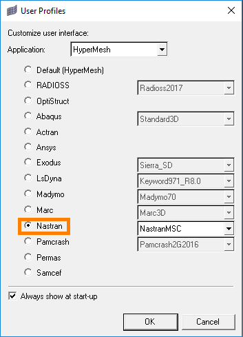
- In the User Profiles window, choose the
Nastran or OptiStruct
format and validate the box:
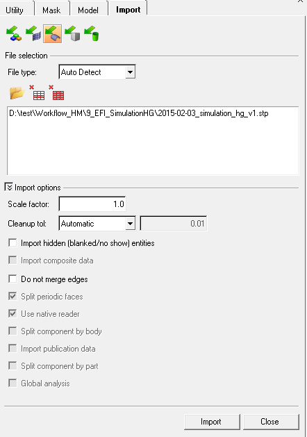
- Import the geometry CAD file:

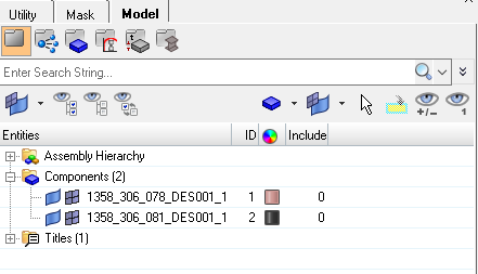
After the import, the components are visible in the Model tab
It is possible to manage the visibility of each component (geometry and mesh)
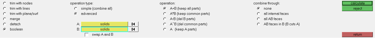
- Make the assembly of the objects in contact to have a conform mesh:
- Choose the operation A+B (keep all parts), in the category advanced
- Choose to combine through none
- Select a solid in A, then the other solid (in contact) in B
- Click on calculate
- Click on return
The faces in contact become yellow
- Create the surface mesh:
- Select all the surfaces to mesh (click on surfs, then on all to mesh all)
- Define the element size (measure the distance between 2 points of the geometry if necessary)
- Choose the elements shape (triangle/quadrangle/…)
- Choose the mesh order (1st or 2nd)
- Etc… (define other parameters if necessary)
- Mesh by clicking on mesh
- Click on return

- It is possible to create the air box in HyperMesh or in Flux.
If you want to create the air box in HyperMesh:
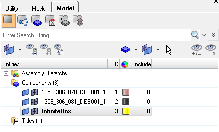
- Create a new component for the air box (click right on
component in the
model tab, then make
create or
duplicate)
-
Create the box:
- Click on base node
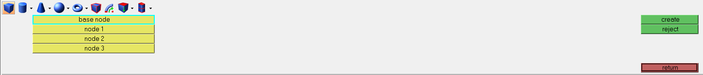
- Enter the coordinates of the 3 vertex
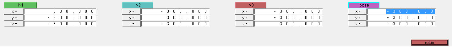
- Click on return
- Click on create
The box is automatically assigned to the component created before
- Create a new component for the air box (click right on
component in the
model tab, then make
create or
duplicate)
- If you created the air box in HyperMesh (previous step):
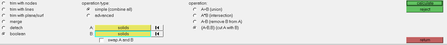
To manage correctly the air box volume mesh, a Boolean operation of separation has to be applied:
- Choose the operation {A-B,B} which is in simple (combine all)
- Select in A the box, and in B the device geometry
- Click on calculate
- Click on return
- Mesh in volume:
- Select all the solids
- Choose the elements type in 2D and 3D
- Choose the option Elems to Surf/Solid Comp to assign a component mesh to the component
- Define the element size value
- Click on mesh
- Click on return

- Create the properties and assign to each component:
- Click on the command properties to create a property. Repeat the operation to create one property per component
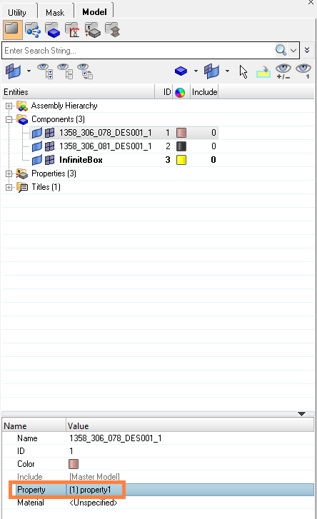
-
Assign to each component a property: for that, select a component in the data tree and choose the property in the window below
This operation allows identifying the volumes at the import in Flux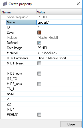
-
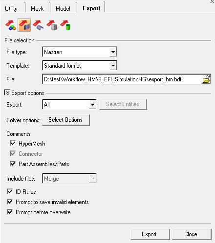
Export the mesh in a Nastran (.bdf,…) or OptiStruct (.fem) file: