Visualization - Road Tools
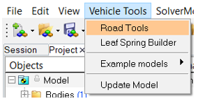
図 1. Road Tools Selection Menu
- Rigid Road
- SoftSoil
Rigid Road
The Rigid Road option provides a way to create a surface graphic for the various Altair Road Files.
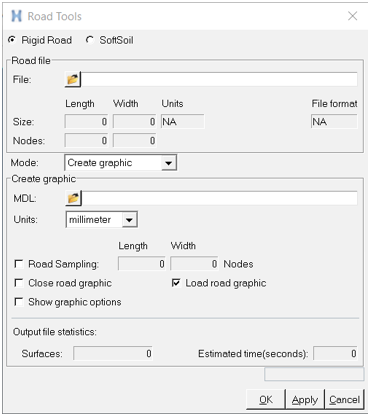
図 2. Rigid Road Dialog
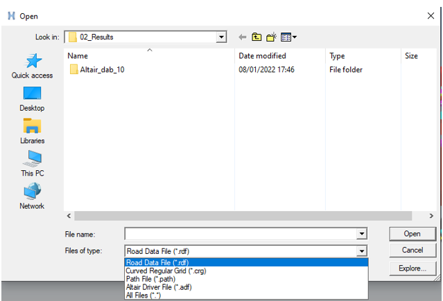 図 3. Road File Path and Type Selection
The MDL option allows the selection of the file path location where the created road graphics are saved.
Road Sampling can be changed as per your requirement to reduce the time and detail level for producing graphics.
If the [GRAPHICS] block is described in road file, it will be used for the road graphics definition.
In the case of a FLAT road type, a checkered grid is created. The grid size is obtained from the LENGTH and WIDTH value available in [GRAPHICS] block. The square size is obtained from the ROAD_INCR value.
$-------------GRAPHICS
[GRAPHICS]
LENGTH = 160000.0
WIDTH = 80000.0
ROAD_INCR = 500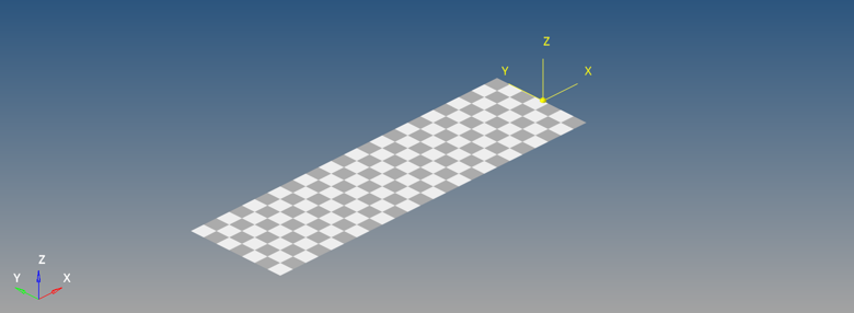
図 4. Checkered Road
SoftSoil
The SoftSoil option provides a way to create a flat surface in MotionView representing the soft soil graphics. The graphic file created with the road tools is sent to MotionSolve where a Grasub is used to mimic a moving carpet-like road that can show soil deformation in HyperView.
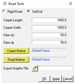
図 5. SoftSoil Dialog
The Export Graphic File option is used to select a path location where the .obj file representing the carpet road is saved.
| Carpet Length | Length of the carpet. |
| Carpet Width | Width of the carpet. |
| Elem dx | Node spacing along the x axis. “0” indicates auto calculated values at runtime. |
| Elem dy | Node spacing along the y axis. “0” indicates auto calculated values at runtime. |
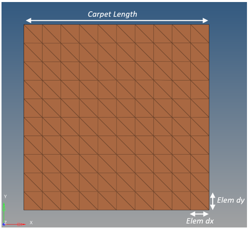
図 6. SoftSoil Carpet
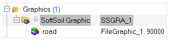
図 7. SoftSoil Graphic System
| Carpet Marker | Center Marker of the SoftSoil Carpet. It can be stationary or a moving
marker. If the marker moves along with the tire, the carpet will be a moving
carpet. In the case where the marker is stationary, the soil deformation will be
visible when the tire passes over the carpet. Default is global marker. In vehicle simulations, the Vehicle Body-CM is an ideal marker to define a moving carpet. |
| Road Marker | A reference marker that is static during the simulation. This marker is used to position and orient the carpet graphic in MotionView. |
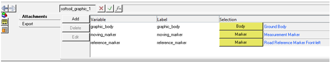
図 8. SoftSoil Graphic System Attachments