Model Setup and Baseline Analysis
The following set of steps completes the analysis setup of the initial model and provides a baseline analysis for comparison with the final optimized structure.
Launch HyperMesh and Set the OptiStruct User Profile
Open the Model
Set Up the Model
Create Carbon Epoxy Material
-
Enter the values shown in Figure 1.
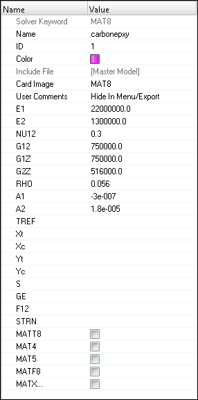
Figure 1.
Create Element Set
Create Basic Plies
-
Create a ply named ply1.
- For Name, enter ply1.
- Set the Material type to ORTHOTROPIC.
- Set Material to carbonepxy.
- For Thickness, enter 0.1.
- For Orientation, enter 0.0.
- Set the Shape selector to Set, then use the Sets selector to select the ply_shape set.
- Select Output results.
- Click Create.
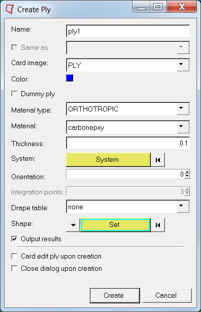
Figure 2.
Create Laminate
-
Click Close to exit
the dialog.
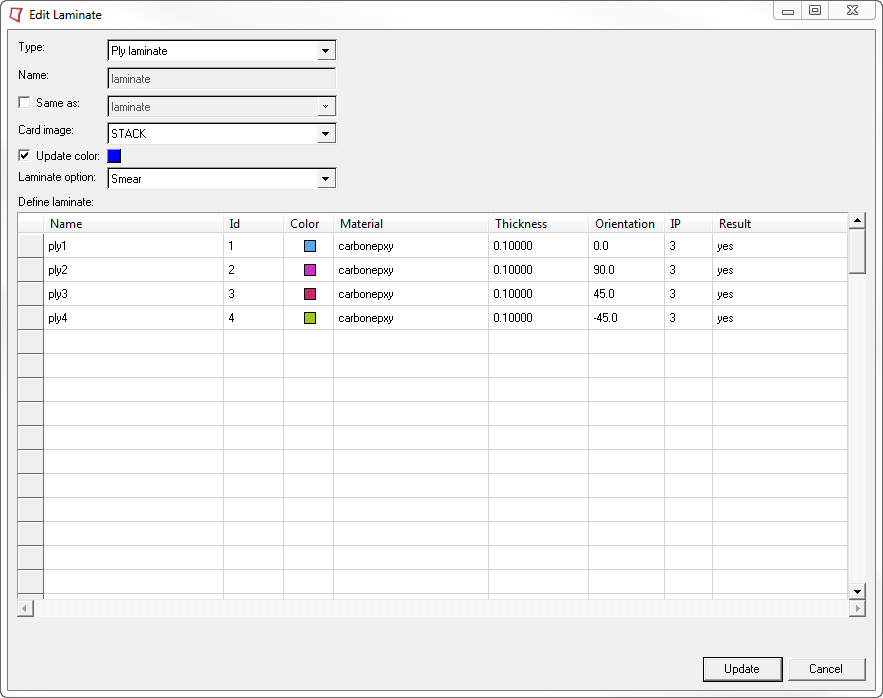
Figure 3.
Create and Assign a Property
-
Create the property, laminate_property.
-
Assign elements to the property, laminate_property.
- In the Model Browser, Properties folder, right-click on laminate_property and select Assign from the context menu.
- In the panel area, use the elems selector to select all elements in the model.
- Click proceed.
Review the Model
-
On the Visualization toolbar, click
 to set the
element visualization mode to 2D Detailed Element
Representation.
This will thicken all shells in the model to their total thickness, displaying them as 3-dimensional representations of their thicknesses.
to set the
element visualization mode to 2D Detailed Element
Representation.
This will thicken all shells in the model to their total thickness, displaying them as 3-dimensional representations of their thicknesses. -
Click
 to set the
layers mode to Composite Layers.
This separates the view into individual plies.
to set the
layers mode to Composite Layers.
This separates the view into individual plies. -
Set the element color mode to By Prop.
This will assist you in determining which plies are which in the layup.Each of the plies in the model are color coded according to the color of its ply as shown in the Model Browser. If all of the plies in the model are the same color, change the ply colors in the Model Browser so that each is different to help differentiate the plies in the modeling window.
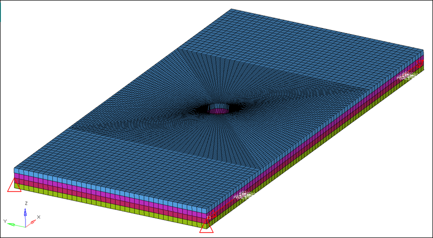
Figure 4.
Create Output Requests
Submit the Job
-
From the Analysis page, click the OptiStruct
panel.

Figure 5. Accessing the OptiStruct Panel
View the Results
-
On the Results toolbar, click
 to open the
Contour panel.
to open the
Contour panel.
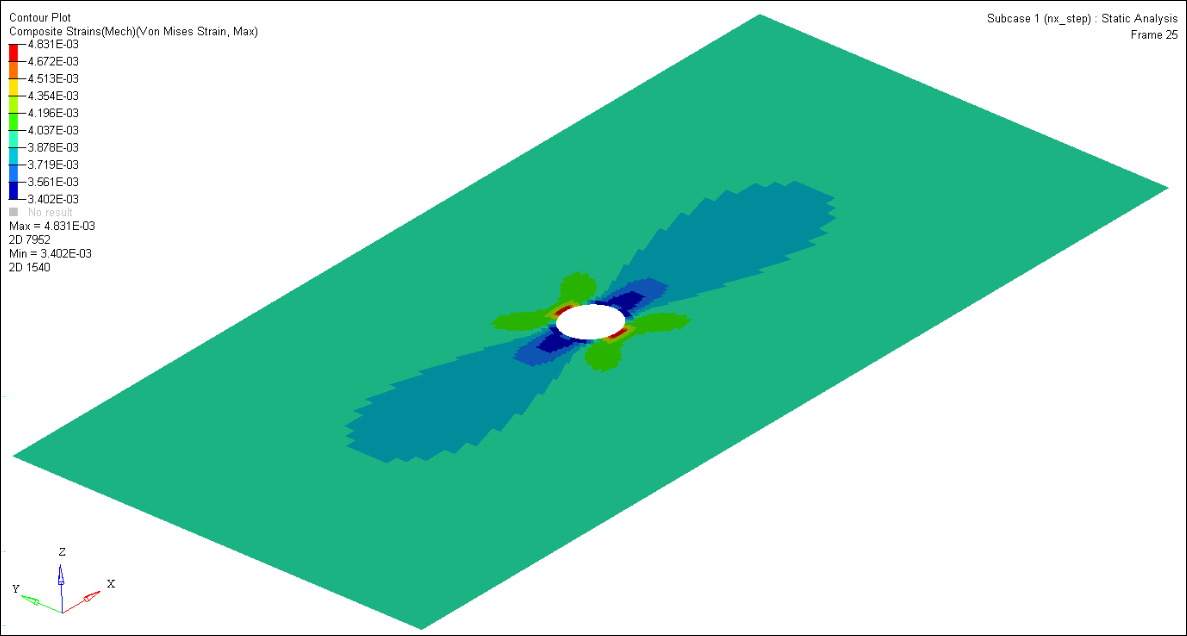
Figure 6.
Deactivate the Composite Visualization Enhancements
-
On the Page Controls toolbar, click
 to close the HyperView session and return to the
HyperMesh client.
to close the HyperView session and return to the
HyperMesh client.
-
On the Visualization toolbar, change the visualization settings.
- Set the element visualization mode to 2D Traditional Element Representation.
- Set the layers mode to Layers Off.
- Set the element color mode to By Comp.