Phase 2: Design Fine Tuning (Size Optimization)

In the second design phase, a size optimization is performed to fine tune the thicknesses of the optimized ply bundles from Phase 1.

To ensure that the optimization design meets the design requirements, additional performance criteria on may be incorporated into the problem formulation. These new criteria will be fiber strain, matrix strain, and mass.

The following is the modified optimization setup:
Design Variables
Ply thicknesses, which have been defined in the size input deck from Phase 1.
Objective
Minimize the total mass.
Constraints
Fiber Strain < 9000 με (microstrain)
Matrix Strain < 7000 με (microstrain)

Manufacturing constraints previously applied are preserved and transferred to the DCOMP card.

Save the Database

  1. From the menu bar, click File > Save As > Model.
  2. In the Save As dialog, enter oht_opti_ph2.hm for the file name and save it to your working directory.

Set Up the Optimization

Edit the Size Design Variables

  1. From the Optimization panel, click the size panel.
  2. Click review.
  3. Select autoply.
  4. In the initial value= field, enter 0.04.
    This is the thickness of four plies.
  5. In the upper bound field=, enter 0.2.
  6. In the lower bound field=, enter 0.0.
  7. Click update to update the design variable.
  8. Repeat the above steps to update the bounds and starting value for each size design variable.
    Note: The DESVARs have the same ID numbers as the design variable property relationship (DVPREL) that they relate to. These ID numbers also refer to the plies created in the previous optimization - in this way, they can easily be cross-referenced.

Edit the Manufacturable Thickness and Initial Value of Each Ply

  1. In the Model Browser, Plies folder, select all plies.
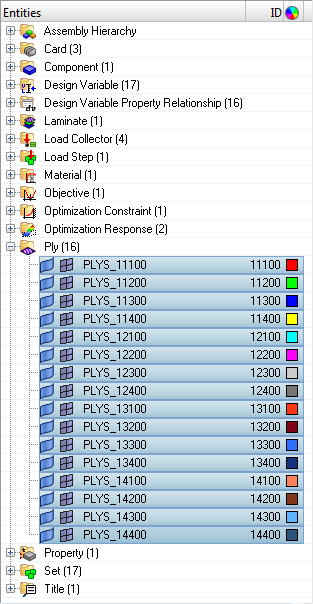
    os3400_ph2_select_all_plies
    Figure 1.
  2. In the Entity Editor, edit the plies.
    1. For TMANUF, enter 0.01.
    2. For Thickness, enter 0.04.
    This changes the values for all plies simultaneously.

Update the Laminate Calculation Type

  1. In the Model Browser, Laminates folder, right-click on laminate and select Edit from the context menu.
  2. In the Laminate Edit dialog, set Laminate option to Symmetric smear.
  3. Click Update to exit.
The laminate option defines the laminate behavior. In this case SMEAR theory is used to define the laminate behavior; that is the A-matrix is calculated exactly since it is stacking sequence independent, the D-matrix is calculated as AT2/12, and finally the B-matrix is set to zero. Adding the Symmetric option to the SMEAR theory just assures a symmetric laminate will be output by adding/removing 2 plies at a time versus 1 ply at a time.

Delete the Existing Responses, Constraints and Objective

  1. In the Model Browser, right-click and select Optimization > Response > Delete from the context menu.
    HyperMesh asks you to confirm the delete.
  2. Click Yes to continue.
When responses are deleted in HyperMesh, all constraints and objectives which depend on those responses are deleted.

Create Size Optimization Responses

The responses of volume, natural frequency, and composite strain are created for size optimization.

  1. From the Analysis page, click the optimization panel.
  2. Click the responses panel.
  3. Create a fiber mechanical strain response.
    1. In the response= field, enter fiber_e.
    2. Set response type to composite strain.
    3. Set component to mechanical.
    4. Set the entity selector to plies, then use the plies selector to select all plies in the mode.
    5. Set the response component to normal 1.
    6. Select all plies.
    7. Click create.

    os3400_ph2_fiber_e_response
    Figure 2. Fiber Mechanical Strain Response
  4. Create a matrix mechanical strain response.
    1. In the response= field, enter matrix_e.
    2. Set response type to composite strain.
    3. Set component to mechanical.
    4. Set the entity selector to plies, then use the plies selector to select all plies in the mode.
    5. Set the response component to normal 2.
    6. Select all plies.
    7. Click create.

    os3400_ph2_matrix_e_response
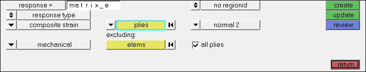
    Figure 3. Matrix Mechanical Strain Response
  5. Create the mass response.
    1. In the response= field, enter mass.
    2. Set response type to mass.
    3. Set type to total.
    4. Click create.
  6. Click return to go back to Optimization panel.

Create Design Constraints

  1. Click the dconstraints panel.
  2. In the constraint= field, enter fiber_e.
  3. Click response = and select fiber_e.
  4. Check the box next to upper bound, then enter 0.009.
  5. Using the loadsteps selector, select nx_step.
  6. Click create.
  7. Create constraint matrix_e on response matrix_e for loadstep nx_step with an upper bound of 0.007.
  8. Click return to go back to the Optimization panel.

Define the Objective Function

  1. Click the objective panel.
  2. Verify that min is selected.
  3. Click response= and select mass.
  4. Click create.
  5. Click return twice to exit the Optimization panel.

Edit the Composite Size Design Variable

  1. From the optimization panel, click the composite size panel.
  2. Select the create subpanel.
  3. Click review.
  4. Select the free-size design variable.
    This DESVAR has been carried over from the previous optimization as a size optimization with manufacturing constraints preserved from the original optimization.
  5. Select the parameters subpanel.
  6. Under laminate thickness, toggle minimimum thickness off to minimum thickness, and enter 0.04.
  7. Click edit.
  8. Review the manufacturing constraints.
    1. Verify PLYPCT is set to restrict 0 and 90-degree plies to between 0.2 and 0.7.
    2. Verify BALANCE is set to 45 and -45 degree plies.
    3. Verify PLYDRP is still set to TOTAL with a PDMAX of 0.33.
  9. Click return to keep these parameters.
  10. Click update.
  11. Click return twice to return to the Analysis page.

Define the Output Request

The output control on composite strain and stress results defined in the previous phase are carried over automatically. OUTPUT,SZTOSH (sizing to shuffling) writes a ply stacking optimization input deck.
  1. From the Analysis page, click the control cards panel.
  2. In the Card Image dialog, click OUTPUT.
  3. Set the final KEYWORD to SZTOSH.
  4. Set the FINAL FREQ to YES.
  5. Click return.

Run the Optimization

  1. From the Analysis page, click OptiStruct.
  2. Click save as.
  3. In the Save As dialog, specify location to write the OptiStruct model file and enter oht_opti_ph2 for filename.
    For OptiStruct input decks, .fem is the recommended extension.
  4. Click Save.
    The input file field displays the filename and location specified in the Save As dialog.
  5. Set the export options toggle to all.
  6. Set the run options toggle to optimization.
  7. Set the memory options toggle to memory default.
  8. Click OptiStruct to run the optimization.
    The following message appears in the window at the completion of the job:
    OPTIMIZATION HAS CONVERGED.
    FEASIBLE DESIGN (ALL CONSTRAINTS SATISFIED).
    OptiStruct also reports error messages if any exist. The file oht_opti_ph2.out can be opened in a text editor to find details regarding any errors. This file is written to the same directory as the .fem file.
  9. Click Close.
The default files that get written to your run directory include:
oht_opti_ph2.out
OptiStruct output file containing specific information on the file setup, the setup of the optimization problem, estimates for the amount of RAM and disk space required for the run, information for all optimization iterations, and compute time information. Review this file for warnings and errors that are flagged from processing the oht_opti_ph2.fem file.
oht_opti_ph2_des.h3d
HyperView binary results file that contain optimization results.
oht_opti_ph2_s#.h3d
HyperView binary results file that contains from linear static analysis, and so on.
oht_opti_ph2_shuffling.*.fem
A ply stacking optimization input deck. The DESVAR and DVPREL cards from the previous stage are removed, and a bare DSHUFFLE card is introduced. The * sign represents the final iteration number.
oht_opti_ph2_shuffling.*.inc
An ASCII include file containing ply stacking optimization data.

View the Results

  1. From the OptiStruct panel, click HyperView.
    HyperView is launched and the results are loaded. A message window appears to inform of the successful model and result files loading into HyperView.
  2. Navigate to the page with the results for oht_opti_ph2_des.h3d.
  3. On the Results toolbar, click resultsContour-16 to open the Contour panel.
  4. Set the Result type to Ply Thicknesses (s).
  5. Select the plot options.

    os3400_ph1_contour_panel_settings
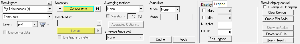
    Figure 4. Ply Thicknesses Contour Plot
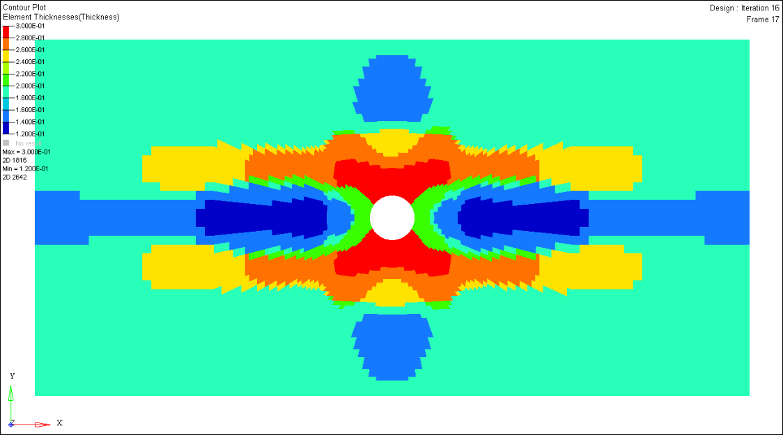
  6. In the Results Browser, select the last iteration.
  7. Click Apply.
An element thickness contour plot (final iteration) after phase-2 size optimization displays.

os3400_ph2_sizing_results
Figure 5.