Run a Binder Sinter Analysis
Run a binder sintering analysis for the selcted print parts.
Before running a binder-sintering analysis, you must first
select the parts to be printed, set up the oven, define the part orientation, and create
setters.
-
Click the
 button on the Analyze
icon.
button on the Analyze
icon.

Tip:
- Click
 on the Analyze icon to view the run status.
Runs that are being processed or that have not been viewed are shown in the
Run Status table.
on the Analyze icon to view the run status.
Runs that are being processed or that have not been viewed are shown in the
Run Status table. - Click
 on the Analyze icon to view the run history.
Runs that have been viewed previously are shown in the Run
History table.
on the Analyze icon to view the run history.
Runs that have been viewed previously are shown in the Run
History table. - The
 icon indicates that the run was
incomplete. Some but not all of the result types may be available. You
should run a new analysis to generate complete results.
icon indicates that the run was
incomplete. Some but not all of the result types may be available. You
should run a new analysis to generate complete results. - To view multiple runs, hold the Ctrl key while selecting runs, then click the View Now button. If several runs are associated with the same part, the result from the most recently completed run for that part will be activated in the modeling window.
- To open the directory where a run is stored, right-click the run name and select Open Run Folder.
Process Parameters
Process parameters impact what result types are available at the end of the simulation, as well as the processing time and accuracy of results.
Basic
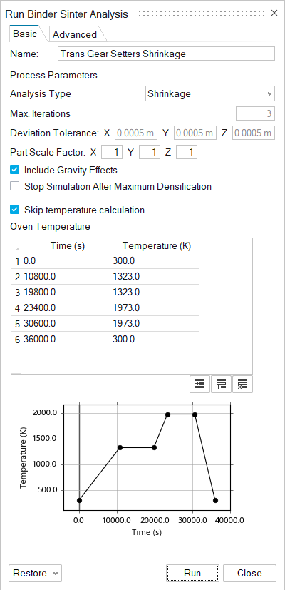
- Analysis Type
- Choose between a shrinkage analysis or a compensation analysis. Compensation analyses will run several iterations to find the optimal compensation for expected deformation/densitization.
- Max Iterations
- Enter the maximum number of iterations the solver will run. The default is 3.
- Deviation Tolerance
- Enter the limit of acceptable deviation. If the part’s deviation reaches this tolerance, the simulation will end. Deviation Tolerance only appears in compensation analyses.
- Part Scale Factor
- Scale the part’s dimensions to compensate for expected shrinkage.
- Include Gravity Effects
- Tell the solver whether to include gravity in its calculations. Gravity is included by default.
- Stop Simulation After Maximum Densification
- If this is checked, the solver will stop the simulation once the part has reached its maximum relative density.
- Skip Temperature Calculation
- If this box is checked, the solver assigns temperature based on the open curve. Otherwise the solver computes the temperature by solving the energy equation.
- Oven Temperature
- Set the oven’s temperature at specified time points, measured in seconds from the start of the simulation.
Advanced
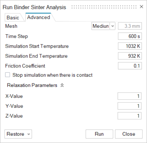
- Mesh
- Set the mesh to fine, medium, or coarse, or define a custom mesh.
- Time Step
- Enter the duration of each time step in seconds.
- Simulation Start Temperature
- Set the temperature at which the simulation will begin. This combined with Simulation End Temperature allows you to run the analysis only on a select portion of the simulation.
- Simulation End Temperature
- Set the oven’s final temperature for the analysis. The solver takes the temperature curve into account and ends the analysis when the temperature is trending down.
- Friction Coefficient
- Defines the friction between the part and the build platform. This affects the part's deformation.
- Relaxation Parameters
- These parameters control the compensation applied at each iteration during a compensation analysis. Enter a value between 0.1 and 10 to change the compensation factor in the simulation. Used only in a compensation analysis.