Contacts
Contacts indicate whether neighboring surfaces should be bonded, contacting, or have no contact.
This tool detects possible contacts in your model. If contacts aren't found, you can manually create contacts between parts.
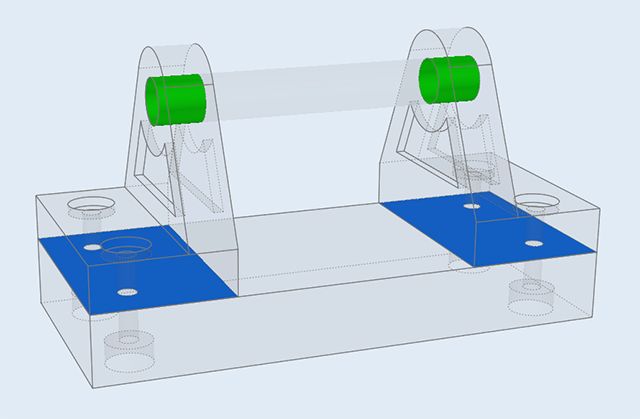
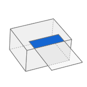
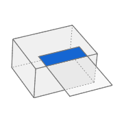
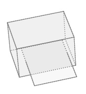
Figure 1. Model with Contacts Defined
Defining Surface Contacts
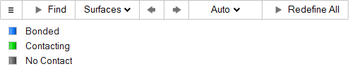
Find neighboring surfaces and designate whether they should be bonded, contacting, or have no contact.
-
On the Structures ribbon, select the Contacts
tool.

-
Select Surfaces on the guide bar.
-
Select a contact to redefine, and change its type in the microdialog.

-
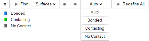
To redefine all contacts of the same type:
- Click the Auto button on the guide bar and select Bonded, Contacting, or No Contact from the list.
-
Click Redefine All to apply changes to the
entire group.
- To automatically detect relevant features when the tool is opened, go to the Preferences under and turn on Autofind.
- If a contact is not detected, try changing the Auto Search Distance under
the Find Options
 on the guide bar.
 - Inspire detects contact between surfaces and solids, but not all cases are considered valid. (View examples of valid and invalid contacts later in this topic).
- If Auto is selected on the guide bar, Inspire automatically determines whether contacts should be bonded or contacting based on the presence of other connections between parts. If there are no fasteners or joints connecting two parts together, they are assumed to be bonded. If fasteners or joints are present, parts are assumed to be contacting.
- Two parts which are in contact in multiple locations must have the same type of contact at each location.
- OptiStruct analysis supports both surface-to-surface and node-to-surface type contacts.
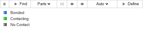
Defining Part-to-Part Contacts
Create contacts between parts manually.
-
On the Structures ribbon, select the Contacts
tool.
-
Select Parts on the guide bar.
-
Select Bonded, Contacting, or No Contact in the microdialog.
- If a contact is not detected, try changing the Auto Search Distance under
the Find Options on the guide bar.
- Inspire detects contact between surfaces and solids, but not all cases are considered valid. (View examples of valid and invalid contacts later in this topic)
Microdialog Options
Click a selected contact to open a microdialog and change the type. The options are Bonded, Contacting, or No Contact.
- Select Bonded if parts are bonded or glued together.
- Select Contacting if there is relative sliding between the parts.
- Select No Contact if parts are close but you don't want them to have contact.
Auto Search Distance
The auto search distance is a global search threshold that uses default tolerances to find locations where joints can be created.
Click the Find Options
menu on the guide bar to change the Auto search
distance. When the checkbox is enabled, it is calculated
automatically.
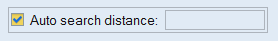
To change the search distance, deselect the checkbox and enter a value in the text box. Any contacts with a minimum gap less than the entered search distance will be found. (The minimum gap is the exact minimum distance between the two parts.)
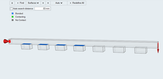
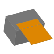
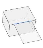
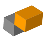
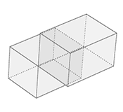
Figure 2. Auto Search Distance
The minimum separation between the beam and the blocks in this model ranges from 0.0 to 0.06 mm. When the search distance is manually set to 0.03 mm, the first four contacts with a minimum separation of 0.03 mm or less are detected.
Fixing Disconnected Groups
Find and review any disconnected groups of parts using the Disconnected Groups tool on the Contacts icon.
Contacts are defined differently depending on which solver you use. With the OptiStruct solver, contacts are defined between parts; with SimSolid they are defined between faces, which may result in a greater number of contacts. If you switch between solvers, you will need to open the Contacts tool, click Find, and then redefine contacts using the appropriate method.

You can find and review any disconnected groups of parts using the Disconnected Groups tool on the Contacts icon.
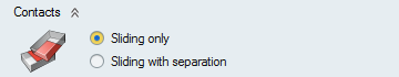
Defining Contacts for Optimization
When running an optimization, you must designate whether contacts should slide, or slide and separate.
Contacts Table
The Contacts table lists all of the contacts in your model including the type of connection and the parts it connects.
Click the ![]() satellite icon on the Contacts tool to display the table.
satellite icon on the Contacts tool to display the table.
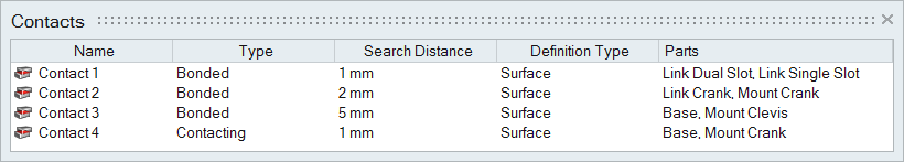
The Search Distance listed in the Contacts table shows the minimum gap (the exact minimum
distance between the two parts). The search distance for an individual contact defined in
this table will override the global Auto search distance defined in the Find Options on
the guide bar.
The table data can be edited with the following actions:
| To | Do this |
|---|---|
| Rename a contact | Select the cell in the table and then click again to make the field editable. |
| Change the connection type | Select the cell in the table and then select a different option from the list. |
| Sort a column | Click the column header. Click repeatedly to toggle between ascending and descending order. |
| Add or remove columns | Right-click on a column header. |
Contact Clearance
Contact clearance is an advanced feature used to either force or prevent contact in cases where there is a slight separation between contacting parts. It is only considered when running an analysis or optimization with the Sliding with Separation option selected.
By default, the contact clearance is set to 0.0, meaning that the parts are always in
contact regardless of the minimum separation. You can change the default value by
clicking the  icon
on the Contacts guide bar.
icon
on the Contacts guide bar.
To edit the contact clearance for an indivudal contact:
-
Click the List Contacts
 satellite icon on the Contacts tool.
-
Right-click a column header on the Contacts Table and select Clearance to add
it to the table.
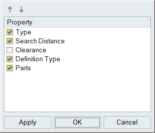
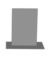
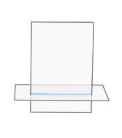
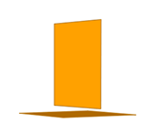
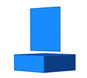
Figure 3. Original Model. There is a 0.5 mm gap between the button and the corresponding contacting part.
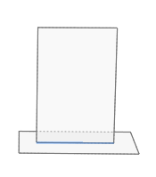
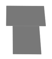
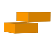
Figure 4. No Contact. Deflection is < 0.5 mm, so no contact occurs.
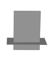
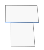
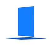
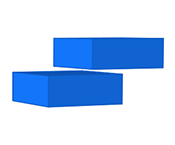
Figure 5. Contact. Deflection is > 0.5 mm, so contact occurs between the parts.
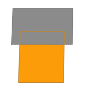
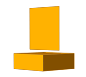
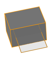
Figure 6. Enforced Contact. Contact is enforced between the parts when clearance is 0.0.
Mouse Controls and Keyboard Shortcuts
| To | Do this |
|---|---|
| Select a contact | Left-click a contact to select it. |
| Select multiple contacts | Hold down the Ctrl key and left-click, or use box selection. |
| Deselect contacts | Hold down the Ctrl key and left-click a selected contact. |
| Deselect all contacts | Left-click on an empty space in the modeling window. |
| Delete part contacts | Select a manually defined part contact in the Contacts table and click Delete. |
| Exit the tool | Right-click and mouse through the check mark to exit, or double-right-click. |
Valid and Invalid Contacts
Inspire detects contact between surfaces and solids, but not all cases are considered valid.
| Geometry | Valid Contact | Description | Type |
|---|---|---|---|
 |
 |
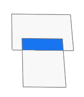
Exact Surface Edge to Surface Face | Surface or Part-to-Part |
 |
 |
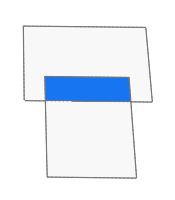
Surface Intersection | Surface or Part-to-Part |
 |
 |
Exact Surface Edge to Exact Surface Edge | Surface or Part-to-Part |
 |
 |
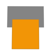
Overlapping Surfaces | Surface or Part-to-Part |
 |
 |
Surface to Midsurface | Surface or Part-to-Part |
 |
 |
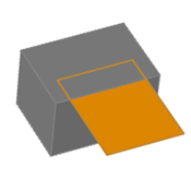
Overlapping Surface and Solid | Surface or Part-to-Part |
 |
 |
Solid to Midsurface | Surface or Part-to-Part |
 |
 |
Exact Surface Edge to Exact Solid Edge | Surface or Part-to-Part |
 |
 |
Surface to Surface at a Distance | Part-to-Part only |
 |
 |
Surface to Solid at a Distance | Part-to-Part only |
 |
 |
Solid to Solid at a Distance | Part-to-Part only |
| Geometry | Invalid Contact | Description |
|---|---|---|
 |
 |
Surface and Solid Intersection |
 |
 |
Exact Solid Edge to Exact Solid Edge |