Tutorial: Basic Sketching
Create a basic sketch.
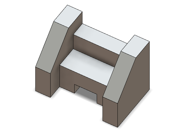
In this lesson, you will learn how to:
- Create and dimension a global sketch
- Extrude a sketch
- Sketch on the face of a model
- Apply planar symmetry
- Trim an object
Create and Dimension a Global Sketch
-
Start Inspire Studio. Or if it is already open, click the
New model tool on the File
icon.

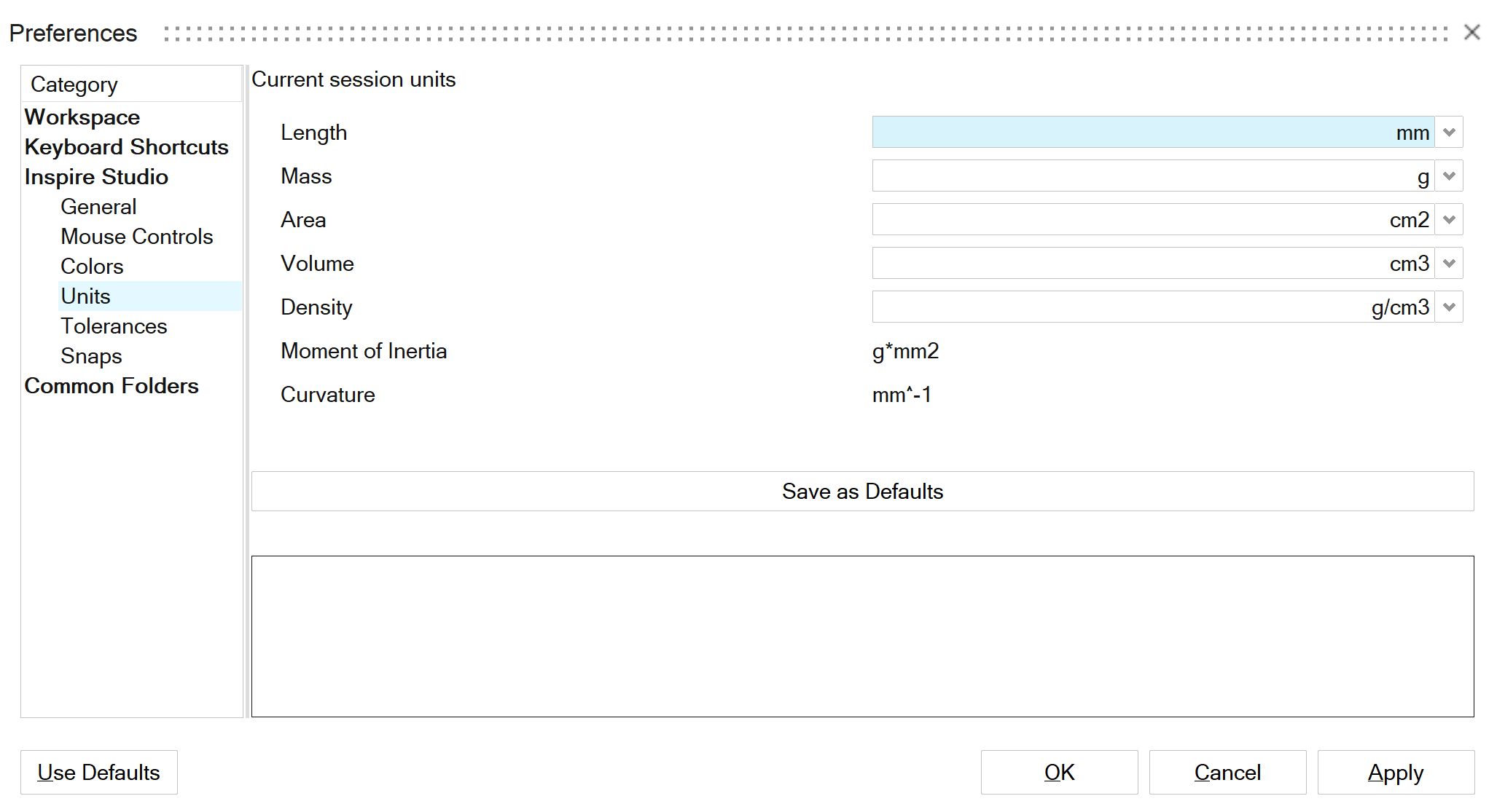
- On the File menu, click the Preferences button.
- Under Inspire Studio > Units, for Length, select mm.
-
Click the Save as Defaults button. Click
Apply, then OK to close.
- On the ribbon, click the Sketching tab.
-
Click the Line icon.
-
Click the Right sketch plane.
.png)
The view automatically aligns orthographically. -
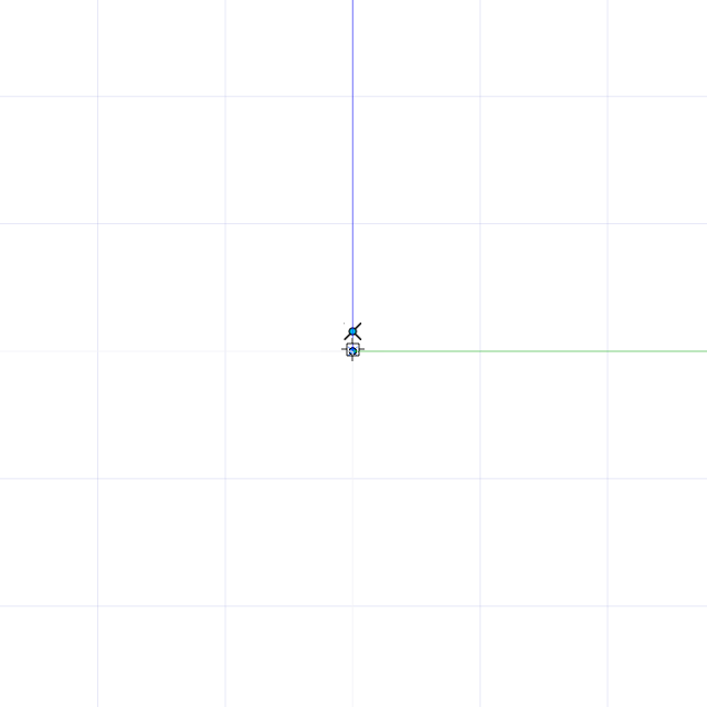
Move the mouse pointer near the global center until it snaps. You should see a
coincident snap icon. Click to insert the first point.
-
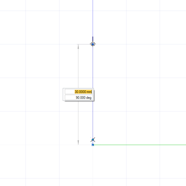
Move the mouse cursor along the z-axis.
A text box appears to input the length.
-
Enter 20, and press Enter.
Note: The value that you enter in the text box creates a true sketch. You can confirm the value once you add dimensions.
-
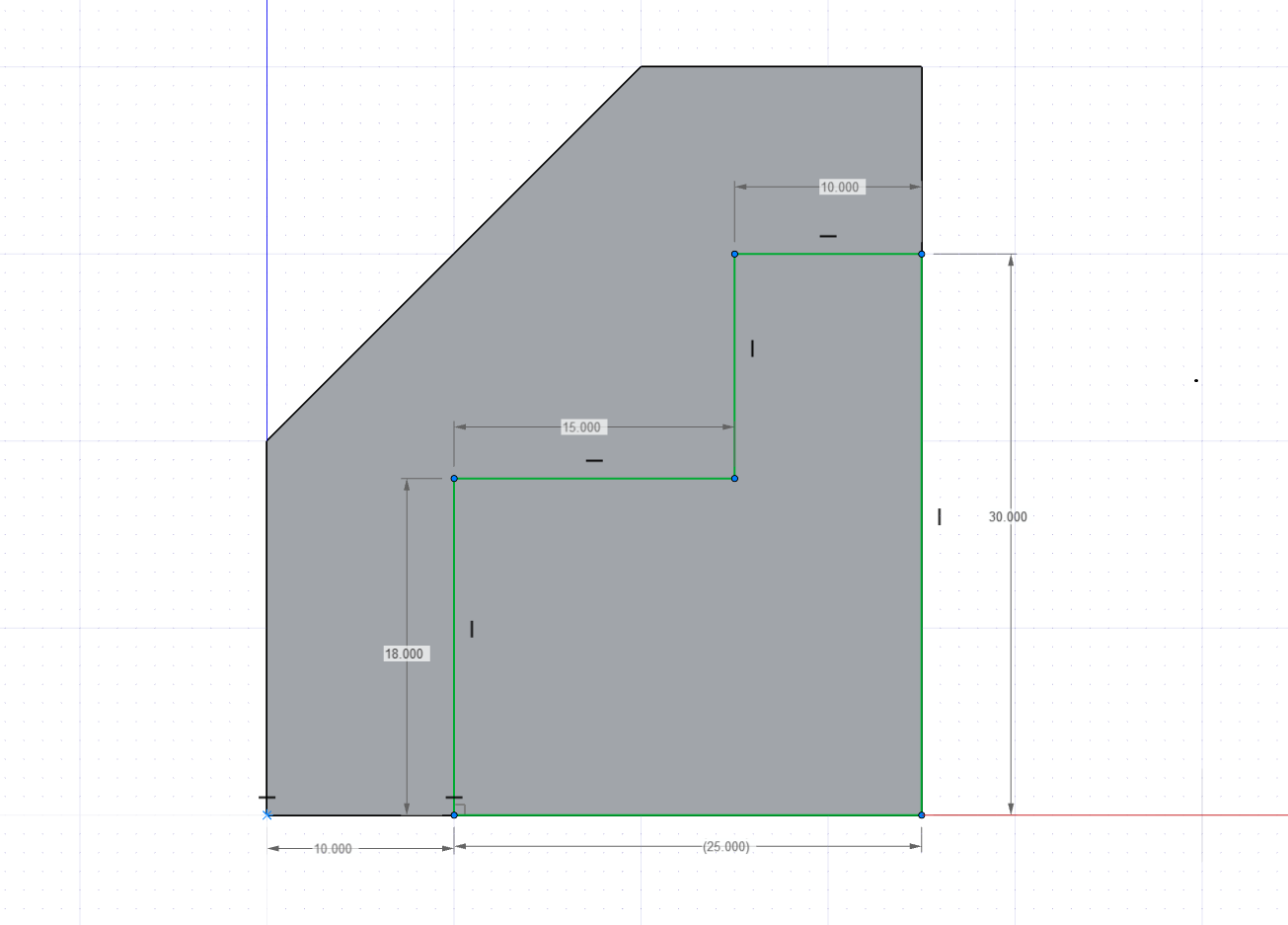
Complete the sketch according to this video:
-
Dimension the sketch according to this video:
- Right-click and mouse through the check mark to exit, or double-right-click.
- Save the file as Level1_Tutorial1.
Extrude a Sketch
-
In the view controls, click the Home
 icon to return to the default orthographic
view.
- Press F to fit the sketch in the view.
-
Open the Extrude tool:
- On the Surfaces tab, click the Extrude icon.
- While holding down Alt, right-click to open the tool belt, and then click the Extrude icon.

-
Modify the sketch curve:
-
Click the sketch curve in the modeling window.
By default, the sketch curve is extruded according to the sketch dimensions.
- Change the extrusion value to 10 mm.
- In the guide bar, select Caps.
-
Click the sketch curve in the modeling window.
- Right-click and mouse through the check mark to exit, or double-right-click.
Sketch on the Face of a Model
- To sketch on the face of an object, select a sketch tool from the ribbon and click a face on the model.
-
Sketch on the face according to the video:
-
Dimension the sketch.
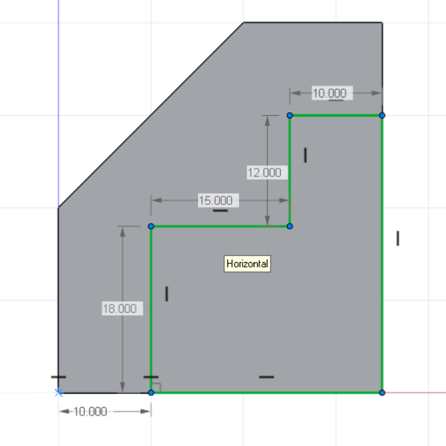
Tip: You may have to apply a horizontal constraint to the origin and first point (10 mm from the origin) to fully define this sketch. -
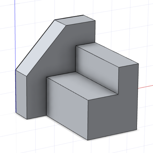
On the Surfaces tab, click the
Extrude icon.

-
Enter a value of 35 mm and add caps.
- Save the file.
- Right-click and mouse through the check mark to exit, or double-right-click.
Apply Planar Symmetry
- On the ribbon, click the Modify tab.
-
In the Symmetry tool group, click the Planar
Symmetry icon.
-
Click the first extrusion. Reposition the symmetry line by dragging and
snapping to the opposite side of the second extrusion, or enter an X value of
27.5 mm. In the guide bar, select Combine
with inputs to join the two objects.
- Save the file.
- Right-click and mouse through the check mark to exit, or double-right-click.
Sketch on Face
- On the ribbon, click the Sketching tab.
-
In the Rectangles tool group, click the
Corner Rectangle icon.
Trim the Object
- On the ribbon, click the Modify tab.
-
Click the Trim icon.

-
Open the sketch from Step 4, Level1_Tutorial1. Select the
two objects in the scene. Select the surfaces to remove, and then click the
green check mark on the guide bar to complete the trim.
Tip: All input objects in the trim tool are treated as a single body. Selecting objects that are not directly in the trim path is a trick to force the trim tool to perform a Boolean union at the end of the operation.
- Right-click and mouse through the check mark to exit, or double-right-click.