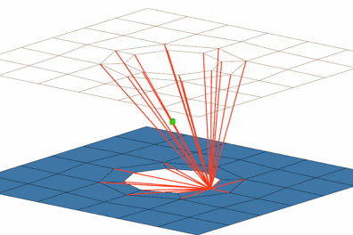
RgdBody (spider + washer)
Creates a RgdBody rigidlink element for the body. It connects to the nearest node to the connector position and then projects to the nearest nodes on the adjoining elements of the connected components.

Figure 1.
View new features for HyperWorks 2022.1.
Learn the basics and discover the workspace.
Discover HyperWorks functionality with interactive tutorials.
Start HyperWorks and configure the applications.
Create, open, import, and save models.
Set up sessions and create report templates.
Solver interfaces supported in HyperWorks.
A solver interface is made up of a template and a FE-input reader.
Browsers supply a great deal of view-related functionality by listing the parts of a model in a tabular and/or tree-based format, and providing controls inside the table that allow you to alter the display of model parts.
Create and edit 2D parametric sketch geometry.
Create, edit, and cleanup geometry.
FE geometry is topology on top of mesh, meaning CAD and mesh exist as a single entity. The purpose of FE geometry is to add vertices, edges, surfaces, and solids on FE models which have no CAD geometry.
Different types of mesh you can create in HyperWorks.
Create and edit 0D, 1D, 2D, and 3D elements.
Create, organize and manage parts and subsystems.
HyperMesh composites modeling.
Create connections between parts of your model.
Use the Connector Browser to view and modify connectors in the current model.
Use the Control Manager to create and edit the various types of controls that will be used later when realizing connectors.
Use the tools in the Create tool set to create connectors, assign controls, and realize.
Use the FE Absorb tools to create connectors from existing mesh that meet specific types of realizations.
View details for different types of realizations.
A list of realization types that can be specified for point connectors.
A list of realization types that can be specified for fastener connectors.
A list of realization types that can be specified for line connectors.
A list of realization types that can be specified for area connectors.
Organize elements into connector groups.
The FE configuration file (feconfig.cfg) is used to define custom welds such as ACM (Area Contact Method) and other special types.
Attachments are an entity to facilitate the ease of joining subsystems.
Abstract information incoming from the CAD hierarchy to robustly create connectors.
Rapidly change the shape of the FE mesh without severely sacrificing the mesh quality.
Create a reduced ordered model to facilitate optimization at the concept phase.
Workflow to support topology optimization model build and setup.
Multi-disciplinary design exploration and optimization tools.
Validate the model built before running solver analysis.
Reduce a full 3D model with axisymmetric surfaces while accounting for imperfections.
Tools and workflows that are dedicated to rapidly creating new parts for specific use cases, or amending existing parts. The current capabilities are focused on stiffening parts.
Tools used for crash and safety analysis.
Airbag solutions offer airbag folder utilities and exports a resulting airbag in a Radioss deck.
Essential utility tools developed using HyperWorks-Tcl.
Import an aeroelastic finite element model with Nastran Bulk Data format.
Framework to plug certification methods to assess margin of safety from the model and result information.
Create evaluation lines, evaluate them, and optimize the interfaces to eliminate squeak and rattle issues.
Panels contains pre-processing and post-processing tools.
Results data can be post-processed using both HyperMesh and HyperView.
HyperGraph is a data analysis and plotting tool with interfaces to many file formats.
MotionView is a general pre-processor for Multibody Dynamics.
MediaView plays video files, displays static images, tracks objects, and measures distances.
TableView creates an Excel-like spreadsheet in HyperWorks.
TextView math scripts reference vector data from HyperGraph windows to automate data processing and data summary.
Create, define, and export reports.
Create connections between parts of your model.
View details for different types of realizations.
A list of realization types that can be specified for fastener connectors.
Creates a RgdBody rigidlink element for the body. It connects to the nearest node to the connector position and then projects to the nearest nodes on the adjoining elements of the connected components.

© 2022 Altair Engineering, Inc. All Rights Reserved.