Element Forces (Vector Plot)
1D element forces and moments are supported as vectors and can be plotted using the Vector panel in HyperView.
This functionality is available for the .op2 and .xdb files. Element force and moment data is requested using the ELFORCE or FORCE case control command in Nastran and OptiStruct.
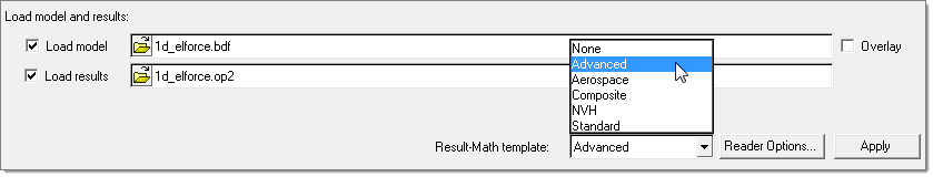
Figure 1.
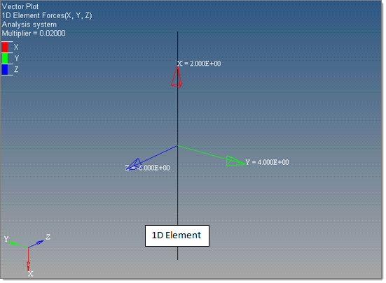
Figure 2.
The 1D Element Forces (v) and 1D Element Moments (v) result types contain X, Y, Z, and magnitude components for all supported 1D element types, which allows plotting force results of multiple element types at the same time.
Supported Element Types
| CBAR (Force) | Component | Result Mapped |
|---|---|---|
| X | Axial Force | |
| Y | Shear Plane 1 | |
| Z | Shear Plane 2 |
| CBAR (Moment) | Component | Result Mapped |
|---|---|---|
| X | Torque | |
| Y | Bending Plane 2 Average of End-A & End-B |
|
| Z | Bending Plane 1 Average of End-A & End-B |
| CBEAM (Force) | Component | Result Mapped |
|---|---|---|
| X | Axial Force Average of GA & GB |
|
| Y | Shear Plane 1 Average of GA & GB |
|
| Z | Shear Plane 2 Average of GA & GB |
| CBEAM (Moment) | Component | Result Mapped |
|---|---|---|
| X | Torque Average of GA & GB |
|
| Y | Bending Plane 2 Average of GA & GB |
|
| Z | Bending Plane 1 Average of GA & GB |
| CROD (Force) | Component | Result Mapped |
|---|---|---|
| X | Axial Force | |
| Y | - | |
| Z | - |
| CROD (Moment) | Component | Result Mapped |
|---|---|---|
| X | Torque | |
| Y | - | |
| Z | - |
| CBUSH (Force) | Component | Result Mapped |
|---|---|---|
| X | Force-X | |
| Y | Force-Y | |
| Z | Force-Z |
| CBUSH (Moment) | Component | Result Mapped |
|---|---|---|
| X | Moment-X | |
| Y | Moment-Y | |
| Z | Moment-Z |
| CGAP (Force) | Plotted | F06 |
|---|---|---|
| X | Comp-X | |
| Y | Shear-Y | |
| Z | Shear-Z |
| CGAP (Moment) | Plotted | F06 |
|---|---|---|
| X | - | |
| Y | - | |
| Z | - |
| CWELD (Force) | Component | Result Mapped |
|---|---|---|
| X | Axial Force FX | |
| Y | Shear Plane 1 FY | |
| Z | Shear Plane 2 FZ |
| CWELD (Moment) | Component | Result Mapped |
|---|---|---|
| X | Torque MX | |
| Y | Bending Plane 2 MY Average of End-A & End-B |
|
| Z | Bending Plane 1 MZ Average of End-A & End-B |
| CFAST (Force) | Component | Result Mapped |
|---|---|---|
| X | Force - X | |
| Y | Force - Y | |
| Z | Force - Z |
| CFAST (Moment) | Component | Result Mapped |
|---|---|---|
| X | Moment - X | |
| Y | Moment - Y | |
| Z | Moment - Z |