Create defined response points that will be automatically used in setting up output
requests in NVH analysis.
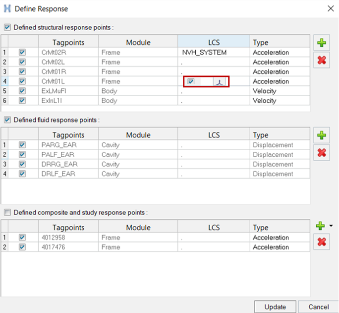
The Response Point Manager is invoked by clicking the icon, which opens the
Define Response dialog.
To add response points, click the icon, which opens the Select Tagpoint Metawidget
dialog, and select a module with tagpoints in it. To delete a response point, highlight the
row corresponding to the response point, and then click the icon. When completed, click Update to save
changes made to response points or click Cancel to discard changes
made since the last update, and exit the dialog. For structural response points, a dynamic
LCS can be added by clicking the entry in the LCS column. This opens the LCS manager, and
you can create a LCS in which response is to be calculated. Figure 1.
 icon, which opens the Select Tagpoint Metawidget
dialog, and select a module with tagpoints in it. To delete a response point, highlight the
row corresponding to the response point, and then click the
icon, which opens the Select Tagpoint Metawidget
dialog, and select a module with tagpoints in it. To delete a response point, highlight the
row corresponding to the response point, and then click the  icon. When completed, click Update to save
changes made to response points or click Cancel to discard changes
made since the last update, and exit the dialog. For structural response points, a dynamic
LCS can be added by clicking the entry in the LCS column. This opens the LCS manager, and
you can create a LCS in which response is to be calculated.
icon. When completed, click Update to save
changes made to response points or click Cancel to discard changes
made since the last update, and exit the dialog. For structural response points, a dynamic
LCS can be added by clicking the entry in the LCS column. This opens the LCS manager, and
you can create a LCS in which response is to be calculated.