Test and CAE Data Handling

Use the ReadVector Builder and CAE Reader utilities to read in and handle CAE files and test data.

Supported Files and Formats

  • Time and frequency-based data formats.
  • Solver file types: Finite Element Analysis (FEA), Computational Fluid Dynamics (CFD) and Multibody System (MBS).
  • File formats: .unv, .iso, .daq, .rsp formats and others.
  • Time steps, result types, requests, and other components of the result data are automatically recognized.

ReadVector Builder

The ReadVector Builder utility helps you create the syntax that reads in the specified CAE data.

To invoke this utility, type readvectorbuilder in the command window.


CAE Reader

The CAE Reader utility is an advanced version of readvectorbuilder that not only prints the command that imports the data, but also imports CAE data with 2D and 3D plots.


Test and CAE Data Import

Four functions enable the importing and testing of CAE data:

Function Description
readvector Reads test and CAE files and returns a data vector. This function reads in a single type of data, and therefore returns a vector.
readmultvectors

With a single command, extracts multiple types of information such as requests (for example nodes or elements from a CAE file; channels from a test file) or several components at once (for example X, Y and Z displacements), and therefore returns an output that is a matrix. Instead of declaring multiple readvectorcommands, readmultvectors accomplishes the same output with fewer operations.

readcae Use readcae to query specific entities that are not necessarily in a range.

readvector and readmultvectors support arguments that can represent a single entity or a range of entities that are to be queried when the initial and final indices are given.

For example, querying an entity list comprised of 1, 10, 15, 16, 17 and 30 could mean a list of channels in a Test file or a list of elements in a CAE File:


When using readvector or readmultvectors, if you provide requests for the initial ID (1 in this case) and the final ID (30), then the requests in between are also read. If you use readcae, only the specified list is read.

 
Note: The functions readvector, readmultvectors and readcae are powered by Altair HyperGraph™ readers, which supports Altair solvers and a variety of other popular formats.
readcae3d

The readcae3d is the dedicated function for reading CAE results when at least one of the following needs to be considered: corner data, averaging method, layer or coordinate system.

For all other use cases, readvector, readmultvectors and readcae are recommended.

Depending on the way that CAE results are queried, model information, which is not possible to retrieve from the default HyperGraph readers, may be required. If model information is required, use readcae3d as its underlying mechanism takes the model into account when contouring the results.

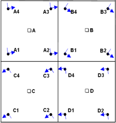
  • Corner Data: Results based on corner data illustrate the expansion of the scope of the standard CAE readers because this abstraction, which is based on the Finite Element Method, relies on both results and model data:


    A, B, C and D represent the centroid of the elements, whereas A1, B1, C1, D1 and the following numbers represent the integration points of each element.

    The calculations at the centroid correspond to what can be visualized with HyperGraph readers, but these calculations come from individual computations performed at the integration points of each element. The results are then extrapolated to generate the corner data.

    When the corner data option is applied and results such as stress are queried, nodal stress results are obtained, and the requests change from elements to nodes.

  • Averaging Method: Due to the limitation of HyperGraph readers, it is not possible to change the averaging method or the coordinate system using solely results available in HyperGraph.

    Nodal averaging of elemental results refers, for example, to the average of all the element corner results passing through a given node.

  • Coordinate Systems: CAE results are usually associated with the global coordinate system, but when another system is used, the results should be transformed accordingly:


    This difference of results, depending on the model, affects mainly the data types and components, which means that subcases, time steps and requests (nodes and elements) are the same regardless of the reading mechanism.

  • Layers: You can display a contour for a specified element layer if the definition for the element layer is available. In some cases, layers do not apply, such as with mass or solid elements.
Note:
  • The function readcae3d is dedicated for CAE files only.
  • Information such as corner data and averaging methods is model dependent.