Creation of 2D profile by a sketch
Introduction
The sketch is an entity defined in a reference plane to create the 2D profile wished using the Sketcher context and his functionalities. Several sketches can thus be created to build different 3D geometric objects by extrusion.
The resulting objects can then be used by all the modeler functionalities manipulating objects (Boolean operations, fillet / chamfer, symmetry / Repetition, cutting, ...)
Structure of a sketch
A Sketch is described by:
- A name (by default SKETCH_1)
- A reference plane on which the profile will be created. (The coordinate system taken into account is the coordinate system associated with the reference plane)
Access
The different accesses of the creation of a Sketch are:
- By menu:
- By icon:

Modification of a sketch
After the creation of a profile in a sketch, from the modeler context the user have the possibility to modify the profile of the sketch by opening the sketcher context and using its.
To open a sketch, in the menu Tools point on Sketch and click on Open a sketch. The sketcher context is opened with the existing 2D profile displayed.
Cycle of life
At any moment the profile of a sketch can be modified.
If the sketch has been used to a geometric operation of extrusion, the modification done on a face of the concerned profile by this extrusion is taken into account.
At the output of the sketcher context the face is re-evaluated as well as the geometric extrusion operation, as well as all geometric operations made after the initial creation of this sketch to ensure the construction tree and so the cycle of life.
Projected lines and points
When the sketch is opened (sketcher context opened), points and lines entities of geometry already created and not belonging to the sketch, can be viewed in the sketcher. Points and lines can be projected orthogonally on the graphical view (in yellow).
These projected entities can be useful to locate and align the profile to create.
Two filters correspond to these entities:
- Display or hide the projected lines by the icon

- Display or hide the projected point by the icon

| Obtained 3D object represented in modeler context | Projection of points and lines of this object, displayed in the sketcher context |
|---|---|
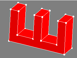
|
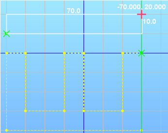
|
Particularity about visibility of sketches
Points lines faces belonging to a sketch appear automatically visible when return to modeler context. Then the user can continue logically with an operation of extrusion.
Contrariwise, to not pollute the graphic display of 3D objects, once these steps done these entities are automatically invisible. These entities reappear as soon as the corresponding sketch is selected in the data tree or if it is selected in the dialog box of the extrusion.
Particularity about entities type of a sketch
Points lines faces of a sketch have a type « No exist », This means that they are not involved in the meshing of the geometry as well as references to entities.
Particularity Import 2D Flux project
After importing 2D Flux project outside the modeler, upon entry in the modeler context, the 2D geometry is automatically converted into a sketch. Then the faces of the 2D project can be extruded.