Helicoidal extrusion of faces
Introduction
The geometric operation Helicoïdal Extrusion of faces allows extruding one or more faces (belonging to the same sketch or belonging to an object), as an helix around an axis.
Color and visibility
Upon creating an extrusion, there is the possibility to specify the color and the visibility of the resulting entities by clicking on:
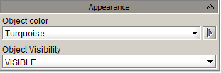
The choice made is applied to the resulting object, but equally to the sub-entities (volume, face, line, point), except for the color of the points and lines that remain in the white color by default for a better visual distinction.
Access
The different accesses of the geometric operation Extrusion are:
- By menu:
- By icon:

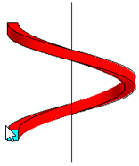
Preview
Upon the creation, a preview of the extrusion can be visualized in the graphic zone. This permits to the user to visualize the object that he will obtain.
The preview is note available in, modification.
Structure of helicoïdal extrusion
The operation Helicoïdal extrusion of faces is describe by:
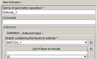
- « Definition » tab
- The sketch containing the faces to extrude (optional)
- A list of faces to extrude
- « Extrusion type » tab
- Type of extrusion
- Definition of the direction of the extrusion axis
- Started point on which the direction of extrusion axis is applied
- Extrusion height
- Extrusion angle (equivalent with number of turns of the helicoïdal extrusion)
- The appearance of resulting objects (color and visibility)
| Dialog box | Illustration |
|---|---|
|
« Definition » tab
|
 |
|
« Extrusion type » tab
|
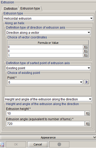
Extrusion axis
The axis around which the helicoïdal extrusion is achieved, is defined by:
- A direction vector:
- By selecting an existing line
- By entering the vector coordinates
- A started point on which the direction vector is applied:
- By selecting an existing point
- By entering the point coordinates
Extrusion angle
The extrusion angle (in degrees) allows defining the number of turns of the helicoïdal extrusion to reach the extrusion height chosen (1 turn = 360°).
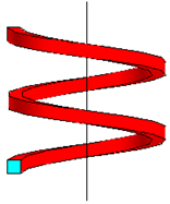
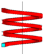
| Examples of helicoïdal extrusion for a same height and different angle values | ||
|---|---|---|
| Angle = 360° ( 1 turn) | Angle = 720° (2 turns) | Angle = 1080° (2 turns) |
|
|
|
Result
The application of a extrusion has as result:
- An object OBJ_EXTRUDE_1 and its sub entities (point, line, face, volume)
- A geometric operation EXTRUDE_1. This geometric operation is a specific entity of the modeler that permits to ensure the cycle of life of the construction (creation - modification - deletion).
- The operation EXTRUDE_1 has been added in the list of geometric operations linked with the object OBJ_EXTRUDE_1 (and also a SWEEP ASSEMBLY if the extruded faces do not belong to a sketch).
Creation of helicoidal extrusion
The process of creation of a helicoidal extrusion of faces is presented in the table below.
| Stage | Description | Tab |
|---|---|---|
| 1 | Opening the dialog box Extrusion | _ |
| 2 |
Choice the name of resulting geometric operation (by default: EXTRUDE_1) |
_ |
| 3 | Choice the sketch (optional) | Definition |
| 4 | Choice the faces to extrude | |
| 5 | Choice the extrusion type (in this case, helicoïdal) | Type of extrusion |
| 6 | Choice the direction vector of the axis extrusion system | |
| 7 | Choice the started point of the axis extrusion | |
| 8 | Choice the extrusion height | |
| 9 | Choice the extrusion angle (equivalent of the number of turns) | |
| 10 | Validation by clicking on OK | _ |
Limitations
Some limitations:
- In modification every fields are editable, except the extrusion type.
- The preview is not available in modification.
- In the case of an extrusion of face does not belong to a sketch, the contour of this face may not modify (must keep the same number of lines an the same lines)