Step 1 : Creation of the computation support
Introduction
In this section, the approach for creating the Support defined by an imported
mesh from rotating machine is presented. It is available through the menu or through the icon ![]() .
.
Creation of the support
The steps in creating the Support defined by an imported mesh from rotating machine are described below. Images of the creation box of the support are also available.
| Step | Action |
|---|---|
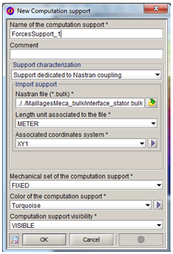
| 1 | Choose the name of the support (+ comment) |
| 2 | Choose the method Support defined by an imported mesh from rotating machine |
| 3 |
Import the Nastran or OptiStruct file (.fem, .bdf, .bulk, etc.) representing the mechanical mesh Attention: the mesh must be cylindrical having an axis parallel to OZ |
| 4 | Choose the measurement unit to be taken into consideration at the import |
| 5 |
Choose the coordinate system* associated to the imported support (see the following sections) The coordinate system choice allows centring the cylindrical mesh on OZ axis (in XYZ1) and base it on z=0 plane in 2D |
| 6 |
Choose the mechanical set of the imported support :
|
| 7 | OK |
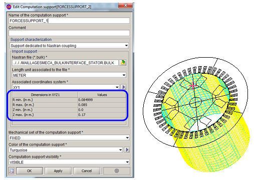
| 8 | Visually verify the placement of the imported support with respect to the geometry. The visualization in 3D is possible also in 2D project. |
| 9 | Re-open the created support box |
| 10 |
Verify the dimensions Rmin, Rmax, Zmin, Zmax of the imported support knowing that :
|
Step 8 to 10:
*Coordinate system of the support: Presentation
Often with mechanical software, the coordinate system in which the motor is defined is not a coordinate system of its own, but the one of the global device (car, …).
With Flux, it is therefore necessary to make the imported support correspond to the geometry. The geometry must have the main axis merging with the axis Z of the XYZ1 coordinate system.
*Coordinate system of the support: In practice (advice)
In practice, if the imported mesh is translated and turned with respect to the Flux geometry, it is very advisable to create two coordinate systems. The approach required is presented in the following table :
| Step | Action |
|---|---|
| 1 | Create a first coordinate system CS_1 defined in the XYZ1 coordinate system of FLUX |
| 2 | Create a second coordinate system CS_2 defined in the CS_1 coordinate system |
| 3 |
Apply in CS_1 according to the needs :
This permits merging the position of the imported support with that of the Flux geometry |
| 4 |
Apply in CS_2 the rotation of the machine around its main axis, which is merged with the axis Z of CS_1 :
|