ACU-T: 5001 Blower - Transient (Sliding Mesh)
Prerequisites
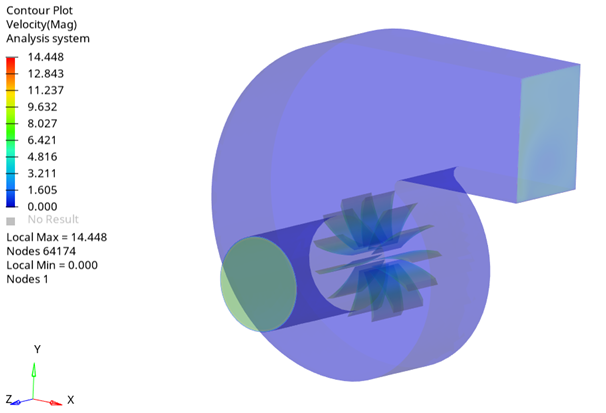
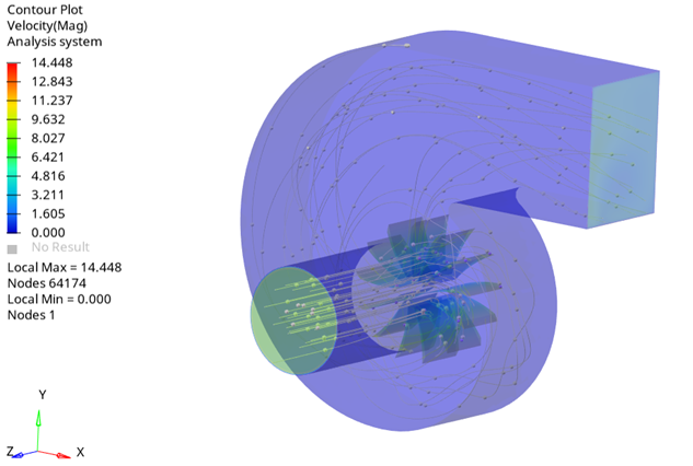
This tutorial provides the instructions for setting up, solving, and viewing results for a transient simulation of a centrifugal air blower utilizing the sliding mesh approach. In order to run this tutorial, you should have already run through ACU-T: 5000 Blower - Steady (Rotating Frame) and kept the solution in your working directory. It is assumed that you have some familiarity with HyperMesh, AcuSolve, and HyperView.
Prior to running through this tutorial, click here to download the tutorial models. Extract ACU-T5001_BlowerTransient.hm from HyperMesh_tutorial_inputs.zip.
Since the HyperMesh database (.hm file) contains meshed geometry, this tutorial does not include steps related to geometry import and mesh generation.
Problem Description

Figure 1.
Open the HyperMesh Model Database
Run the Steady State Simulation
Set the Transient Simulation Parameters
Set the General Simulation Parameters
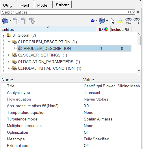
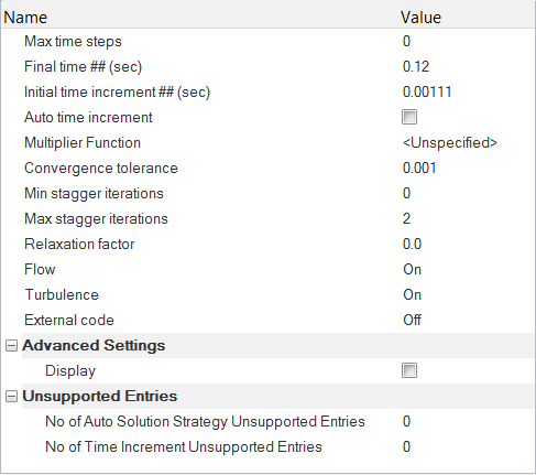
Specify the Solver Settings
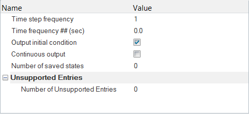
Set the Nodal Output Frequency
Define Mesh Motion and Set Up Boundary Conditions
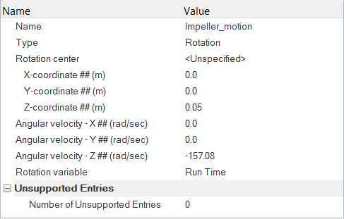
Create Mesh Motion
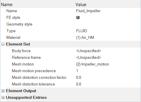
Modify the Boundary Conditions
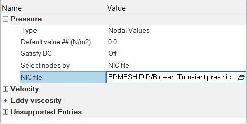
Specify the Nodal Initial Conditions
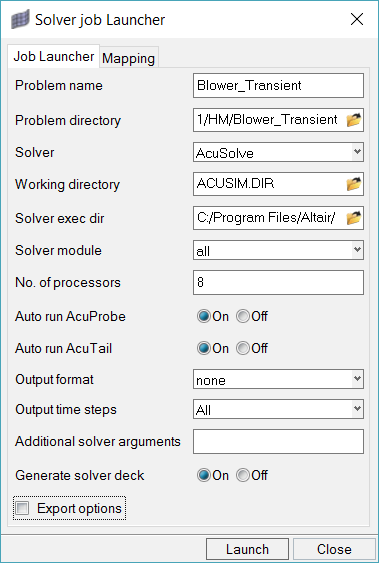
Compute the Solution
Post-Process the Results with HyperView
Open HyperView and Load the Model and Results
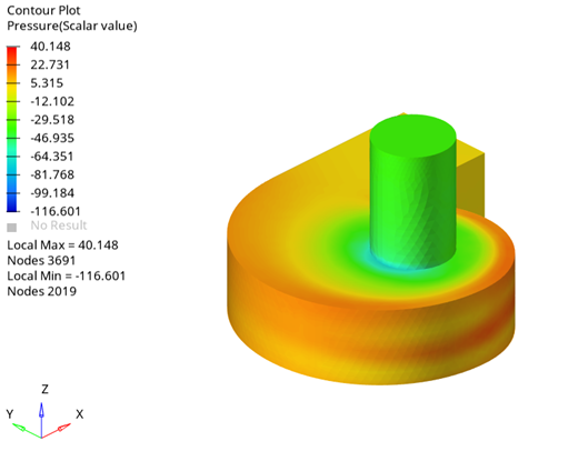
Create a Pressure Animation
Create Streamlines
Summary
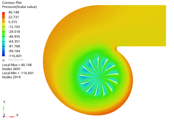
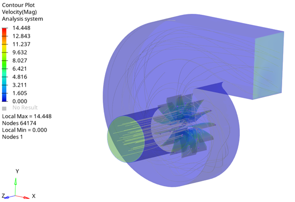
In this tutorial, you successfully learned how to set up and solve a transient simulation of a centrifugal air blower using the sliding mesh approach. You started by importing the meshed geometry and then ran the steady state simulation. Then, you used the steady state result as the starting point for the transient simulation using the AcuProj tool to specify the nodal initial conditions and then solved the transient simulation using the sliding mesh approach instead of the moving reference frame approach. Once the transient solution was computed, you launched HyperView and created an animation of pressure contours and streamlines.

 on the Standard Views toolbar.