ACU-T: 5201 Coupled Simulation of a Check Valve using AcuSolve and MotionSolve
Prerequisites
This tutorial introduces you to the workflow for setting up an AcuSolve-MotionSolve co-simulation using HyperWorks CFD. Prior to starting this tutorial, you should have already run through the introductory tutorial, ACU-T: 1000 Basic Flow Set Up, and have a basic understanding of HyperWorks CFD and AcuSolve. To run this simulation, you will need access to a licensed version of HyperWorks CFD, MotionSolve, and AcuSolve.
Prior to running through this tutorial, click here to download the tutorial models. Extract ACU-T5201_pressureCheckValve.x_t and Valve_model.xml from HyperWorksCFD_tutorial_inputs.zip.
Problem Description

Figure 1. Schematic of Check Valve with Spring-Loaded Shutter
The pipe has an inlet diameter of 0.08 m and is 0.3 m long. The check-valve assembly is 0.085 m downstream of the inlet. It consists of a plate 0.005 m thick with a centered orifice 0.044 m in diameter and a shutter with an initial position 0.005 m from the opening, simulating a nearly closed condition. The shutter plate is 0.05 m in diameter and 0.005 m thick. The shutter plate is attached to a stem 0.03 m long and 0.01 m in diameter. The mass of the shutter and stem is 0.2 kg and its motion is affected by a virtual spring with a stiffness of 2162 N/m. The motion of the valve shutter is limited by a stop mounted on a perforated plate downstream of the shutter.
Note that AcuSolve's internal rigid-body-dynamics solver is not able to simulate contact. Therefore, this problem is formulated to avoid contact between the valve and the stop.
- Scale up the fluid forces calculated by AcuSolve
by a factor of 12 to represent the full load on the device when the
displacement of the body is computed.
Using this approach, the full stiffness of the valve spring is used in the rigid-body solution, and the full mass of the valve is used.
- Scale down the mass of the valve and the stiffness of the spring to by a
factor of 12 to match the fraction of the valve geometry to be
modeled.
Using this approach, the loading passed to the rigid-body solver is not scaled.
This second approach is used in this tutorial; the scaled mass of 0.0167 kg and the scaled stiffness of 180.1667 N/m will be used
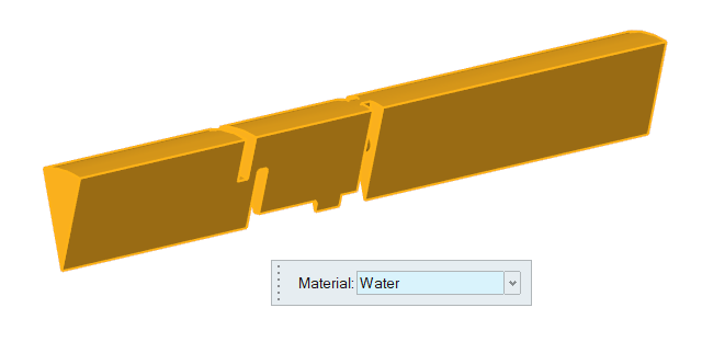
The fluid in this problem is water, which has a density (ρ) of 1000 kg/m3 and a molecular viscosity (μ) of 1 X 10⁻³ kg/m-sec.
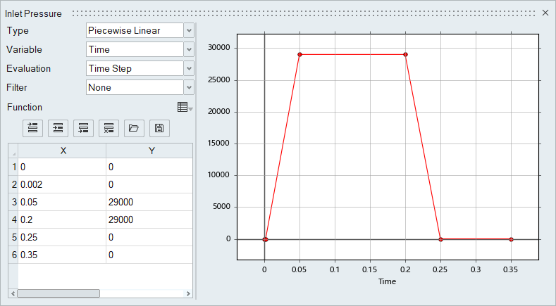
At the start of the simulation, the flow field is stationary. Flow is driven by the pressure at the inlet, which varies over time as a piecewise linear function shown in Figure 2. As the pressure at the inlet rises, the flow will accelerate as the valve opens. The turbulence viscosity ratio is assumed to be 10.
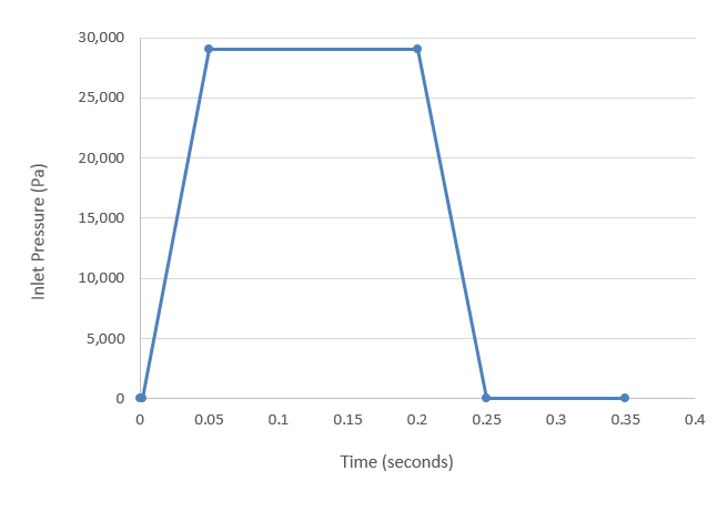
Figure 2. Transient pressure at the inlet
Prior simulations of this geometry indicate that the average velocity at the inlet reaches a maximum of 0.98 m/s. At this velocity, the Reynolds number for the flow is 78,400. When the Reynolds number is above 4,000 it is generally accepted that flow should be modeled as turbulent.
Note that the initial conditions of the flow are actually laminar; however, the increase in flow velocity and flow around the valve shutter is expected to cause a rapid transition to turbulent conditions. Therefore, the simulation will be set up to model transient, turbulent flow. When performing a transient analysis, convergence is achieved at every time step based on the defined stagger criteria. Mesh motion will be modeled using arbitrary mesh movement (arbitrary Lagrangian-Eulerian mesh motion).
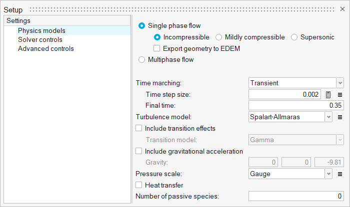
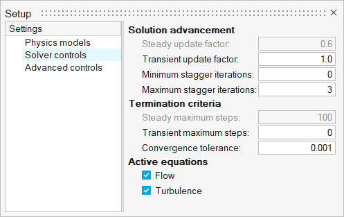
For this case, the transient behavior of interest occurs in the time it takes for the pressure to ramp up and ramp back down, which is given by the transient pressure profile. To allow time for the spring to recover additional time will be simulated. For this tutorial 0.1 s is added after the pressure drops back to initial conditions for a total duration of 0.35 s.
Another critical decision in a transient simulation is choosing the time increment. The time increment is the change in time during a given time step of the simulation. It is important to choose a time increment that is short enough to capture the changes in flow properties of interest, but does not require unnecessary computation time. The change in inlet pressure from initial conditions to maximum occurs over 0.048 s. A time increment of 0.002 s would allow for excellent resolution of the transient changes without requiring excessive computational time.
Start HyperWorks CFD and Create the HyperMesh Model Database
Import and Validate the Geometry
Import the Geometry
Validate the Geometry
Set Up Flow
Set Up the Simulation Parameters and Solver Settings
Create a Multiplier Function for the Inlet Pressure
Assign Material Properties
Define Flow Boundary Conditions
Set Up Motion
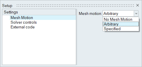
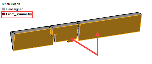
In this step, you will activate the mesh motion and define the rigid body motion for the valve wall. Then, you will define the mesh displacement boundary conditions for the symmetry surfaces.
Define the Mesh Motion Type
Define the Mesh Displacement Boundary Conditions
Generate the Mesh
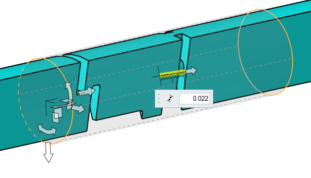
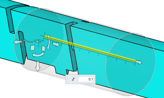
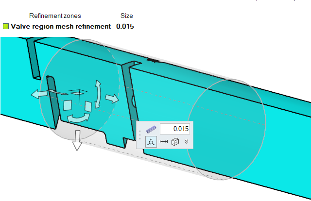
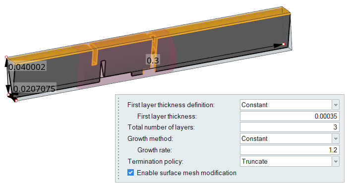
In this step, you will define the mesh controls and then generate the mesh.
Define the Zone Mesh Controls
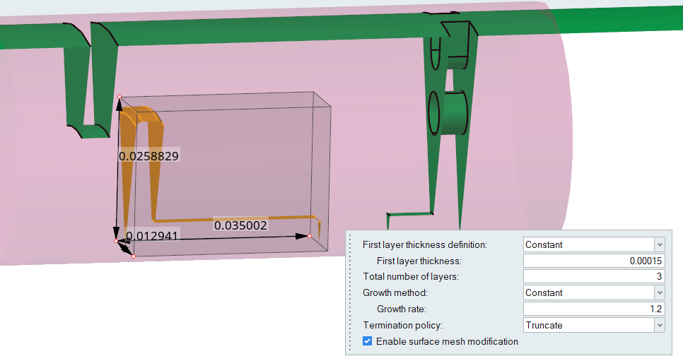
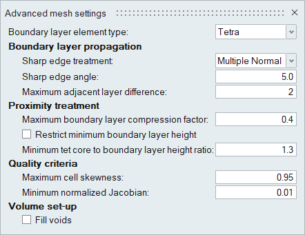
Define the Boundary Layer Controls
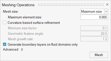
Generate the Mesh
Compute the Solution
Define Nodal Outputs
Run AcuSolve
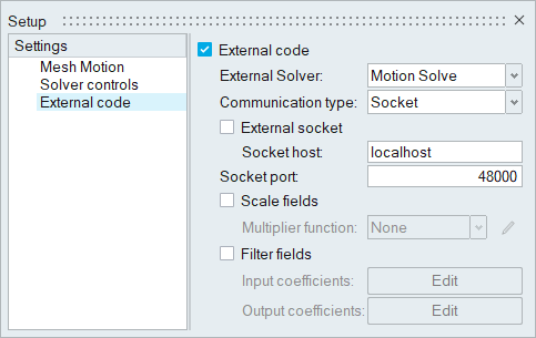
Run MotionSolve
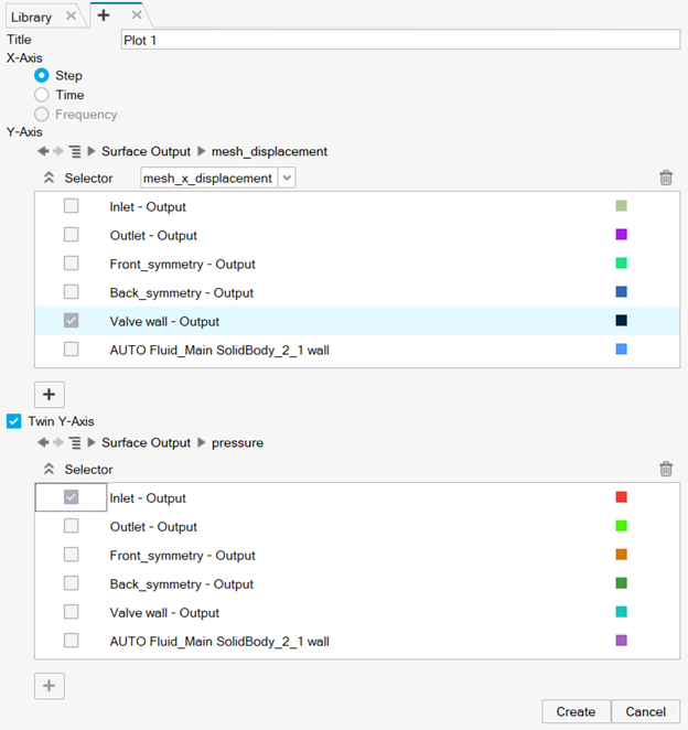
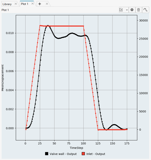
Monitor the Results
Post-Process the Results with HW-CFD Post
Create an Animation of Velocity Magnitude
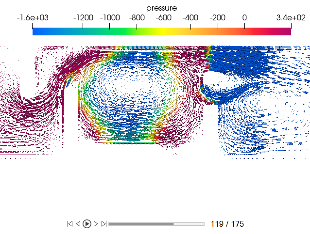
Display Pressure Contours and Velocity Vectors on a Section Cut
Summary
In this tutorial, you learned the basic workflow to set up a co-simulation using AcuSolve and MotionSolve. The tutorial introduced you to the steps involved in setting up external code communication between AcuSolve and MotionSolve using HyperWorks CFD, and then running the simulation and post-process the results using HyperWorks CFD Post. You also learned how to create a vector plot on an existing contour plot on a cut plane.
