Aeroelasticity Browser
Use the Aeroelasticity Browser to build a model for three of the aeroelasticity solution sequences for Nastran (MSC) users.
From the menu bar, click .
The AeroModule, SolutionJobSetup and StructureModule folders organize all of the keywords used to define the aerospace model and setup the solution job. Right-click on a folder and select Create from the context menu to begin creating cards. Use the Entity Editor to define each of the corresponding attributes for the cards.
AeroModule
The AeroModule folder organizes all of the keywords that define the aerospace model.
SolutionJobSetup
- SOL 144: Static Aeroelastic Response
- SOL 145: Aerodynamic Flutter
- SOL 146: Dynamic Aeroelastic Response
StructureModule
The StructureModule folder organizes all of the control structural entities needed for the structure definition. Using the browser you can also define or edit structural entities.
- CAERO1 panels (as special components)
- Splines (SPLINEx)
- Monitor Points (MONPNTx)
- Control Surfaces (AESURF)
- Sets and Groups (AELIST, SET1, AECOMP)
- Flight load definition, such as GUST, FLUTTER and AEFORCE
- AERO/AEROS configuration data, such as ref chord and area
- Factor table data, such as AEFACT, FLFACT, MKAEROx, UXVEC and TRIM
Aero (CAERO1)
- Global, aerospace or user-defined coordinate system for modeling
- Select up to four locations to define the domain for the panel
- Either bias meshing by selecting AEFACT tables or uniform meshing by selecting number of span and chord elements (it can also be a combination).
- Aero panel, property, grid and element numbering pattern is internally followed as per Nastran solver requirements
- Measures are taken to ensure the flow direction is not in the span direction
- The command *createCAERO1() was developed for batch modeling and scripting
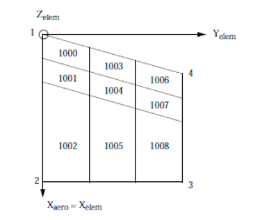
Figure 1.
- Define your own ID and Title by overriding the default values.
- The image icon provides more information about the numbering system and pattern to be followed while meshing CAERO1. For example, the start node and element ID should be the same as the component ID. Numbering should be sequentially incremented in the chord direction and continued in the span direction.
- Define the Flow Direction.
- Mesh control can be done by selecting tables (AEFACT tables) for chord and/or span. You can either select number of chords or span elements. Chord is the direction along flow (point 1 and point 2). Span is the direction along point 1-4.
- You can select Point1 (origin). Location information is extracted from the selected point/node, and the same can be modified by editing the text field.
- For the edge length 1-2 and 3-4, you can select the location by node or point. The selected location information is used to calculate edge length only.
- Point four is used to find the spanning direction and spanning length 1-4.
- After you select all of the necessary data, clicking Create Mesh will mesh the selected domain with AEGRID nodes and AEQUAD4 elements. Per solver requirements, nodes and elements are not explicitly exported into BDF, but other references such as SPLINE, AEGRID AESURF will have their reference.
Bias meshing is supported, which is selected as table of data from AEFACT entities. AEFACT data needs to be pre-created and selected. Biasing can be in only one or both directions.
Aero Body (CAERO2)
- The Body ID and Title are defined by default. You can change these.
- Selection of two points define the axis of the body
- Mesh controls can be defined to identity number of body. Interference elements can be defined and internally required AEFACT tables will be created for the solution.
- Half width is the radius of the body at different locations. Varying cross sections can be defined by providing a comma separated half width in the Num Interference section. Missing data will be repeated with lost data entered.
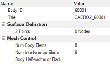
Figure 2.
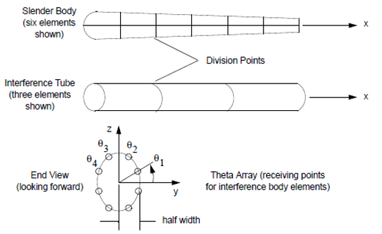
Figure 3.
Splines
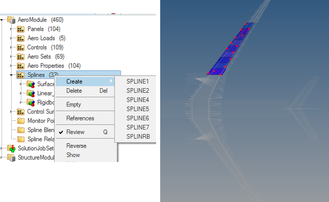
Figure 4.
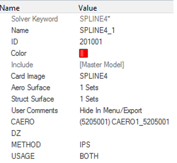
Figure 5.
Aero Control Surface Definition
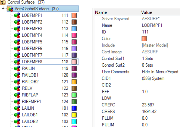
Figure 6.
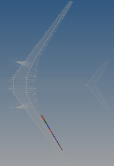
Figure 7.
Monitor Point Definition
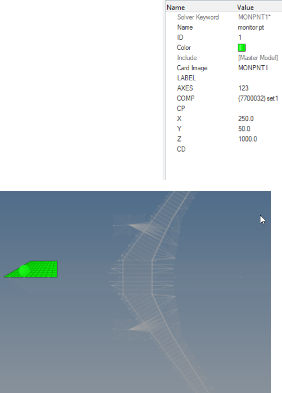
Figure 8.
Aero Loads
FLUTTER, GUST and AEFORCE types of loading definition are created under the loading section in the Aeroelasticity Browser.
Properties, Sets and Controls
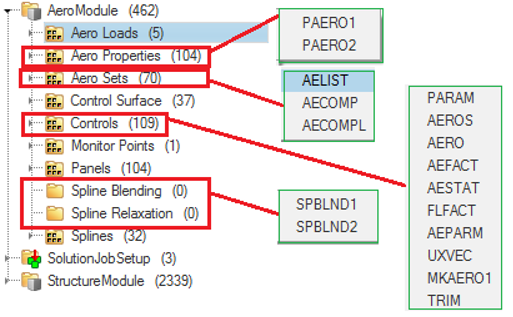
Figure 9.